Advertisement
Table of Contents
- 1 Pldpro Installation
- 2 Electrical Connection
- 3 Configuring the Address
- 4 Pco: Assigning the List of Private and Shared Terminals (for Plan Mode)
- 5 Fault Signals
- 6 Displaying Status of Network and Firmware Release
- 7 Contrast Adjustment and Firmware Version
- 8 Technical Specification
- Download this manual
+050001840 - rel. 1.2 - 16.12.2013
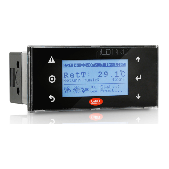
pLDPRO
PLD**GFP00 Interfaccia utente / User interface
Dimensioni / Dimensions (mm)
drilling template
71x29 mm
76 mm
34.4 mm
38.4 mm
Montaggio a pannello /
Panel mounting terminal
Connessioni elettriche / Electrical connection
Smaltimento del prodotto: l'apparecchiatura (o il
prodotto) deve essere oggetto di raccolta separata in
conformità alle vigenti normative locali in materia di
smaltimento. / Disposal of the product: the appliance (or
the product) must be disposed of separately in accordance
with the local waste disposal legislation in force.
Il display grafi co pLDPRO è un dispositivo elettronico,
compatibile con i precedenti terminali della linea PGD1,
che consente la completa gestione della grafi ca tramite la
visualizzazione di icone (defi nite a livello di sviluppo software
applicativo) e la gestione di font internazionali di due
dimensioni: 6x8 e 12x16 pixels e segnale acustico attivabile
da buzzer. Il software applicativo è residente soltanto sulla
scheda pCO, il terminale non ha bisogno di nessun software
aggiuntivo in fase di utilizzo. Inoltre il terminale off re un ampio
range di temperatura di funzionamento (-20T60 °C) e il frontale
garantisce un elevato grado di protezione (IP65).
Installazione pLDPRO
Questo terminale è stato progettato per il montaggio a
pannello; la dima di foratura deve avere dimensioni di
71x29mm come indicato in Fig. 1. Per l'installazione seguire le
istruzioni riportate di seguito:
• Inserire il terminale nell'apertura, e fi ssare il dispositivo al
pannello utilizzando due staff e di plastica scorrevoli laterali,
come mostrato in Fig.2.
• Infi ne, installare la cornice a scatto.
Connessioni elettriche
• Collegare il cavo telefonico (cod. S90CONN00 *) dal controllo
pCO al connettore (RJ11) posto sul retro del terminale. Come
indicato in Fig.3
Confi gurazione indirizzo
È possibile confi gurare l'indirizzo del terminale solo dopo aver
fornito alimentazione allo stesso tramite il connettore telefonico
RJ11 (il valore preimpostato in fabbrica è 32). Per entrare in
modalità confi gurazione premere contemporaneamente i tasti
+↓+↑e (sempre presenti in tutte le versioni) per almeno
5 secondi; verrà visualizzata la maschera di Fig. 4 con il cursore
lampeggiante nell'angolo in alto a sinistra:
• Per modifi care l'indirizzo del terminale (display address
setting) premere una volta il tasto : il cursore si sposterà sul
campo indirizzo (nn).
• Tramite i tasti ↓↑selezionare il valore voluto, e confermare
ripremendo il tasto . Se il valore selezionato è diverso da
quello memorizzato precedentemente apparirà la maschera
di Fig. 5 e il nuovo valore verrà memorizzato nella memoria
permanente del display.
Fig. 1
Se si imposta il campo nn al valore 0, il terminale comunicherà
con la scheda pCO usando il protocollo "punto-punto" (non
pLAN) e il campo "I/O Board address: xx" scompare in quanto
privo di signifi cato.
pCO: assegnazione lista terminali privati e
condivisi (per modalità pLAN)
A questo punto, se fosse necessario modifi care la lista dei
terminali associata ad ogni singola scheda pCO, si dovrà
seguire la seguente procedura:
• entrare nella modalità confi gurazione con i tasti
+↓+↑, come descritto nel paragrafo precedente;
• premere il tasto fi no a che il cursore si posiziona sul
campo xx (I/O board address) Fig. 4;
• tramite i tasti ↓↑scegliere l'indirizzo della scheda pCO
Fig. 2
desiderata. I valori selezionabili saranno solo quelli delle
schede pCO eff ettivamente in linea. Se la rete pLAN non
funziona correttamente, oppure non è presente nessuna
scheda pCO, non sarà possibile modifi care il campo che
mostrerà solo "—";
• premendo ancora una volta il tasto verranno visualizzate
in sequenza le maschere di Fig. 5;
• anche qui il tasto muove il cursore da un campo all'altro e i
pLAN
tasti ↓↑ cambiano il valore del campo corrente. Il campo
P:xx mostra l'indirizzo della scheda selezionata; nell'esempio
di fi gura è stata selezionata la 12;
• per uscire dalla procedura di confi gurazione e memorizzare i
dati selezionare il campo "OK ?" impostare Yes e confermare
con il tasto .
Fig. 3
I campi della colonna "Adr" rappresentano gli indirizzi dei
terminali associati alla scheda pCO di indirizzo 12, mentre la
colonna Priv/Shared indica il tipo di terminale.
Nota: i terminali della linea pLDPRO non possono essere
confi gurati come "Sp" (shared printer) in quanto privi dell'uscita
stampante. Se il terminale rimane inattivo (nessun tasto
premuto) per più di 30 secondi esce automaticamente dalla
procedura di confi gurazione senza memorizzare gli eventuali
cambiamenti.
The pLDPRO graphic display is an electronic device that is
compatible with the previous PGD1 line terminals; it allows
complete management of graphics by the display of icons
(defi ned at application software development level), and
the management of international fonts, in two sizes: 6x8 and
12x16 pixels, and acoustic signal through piezoelectric buzzer
as well. The application software resides on the pCO controller
and therefore the terminal does not require any additional
software for operation. Furthermore, the terminals feature a
wide operating temperature range (-20T60 °C) , the index of
protection of front panel of IP65.
pLDPRO Installation
This terminal has been designed for panel installation; the
drilling template measures 71x29mm, as shown in Fig.1. For
installation, proceed as follows:
• Insert the terminal into the opening, and fasten the device
to the panel using two lateral sliding plastic brackets, as
shown in Fig.2.
• Finally, fi t the click-on frame
Electrical connection
• pLAN: Connect the telephone cable (code S90CONN00*)
from the pCO controller to the connector provided (RJ11)
on the rear of the terminal. As shown in Fig.3
Confi guring the address
The address of the terminal can be confi gured only after
having connected the power supply, using the RJ11 telephone
jack (the factory default value is 32).
To access confi guration mode, press the
together and hold them for at least 5 seconds; the screen
shown in Fig. 4 will be displayed, with the cursor fl ashing in
the top left corner:
• To change the address of the terminal (display address
setting), press the button once, the cursor will move to
the address fi eld (nn).
• Use the ↓↑ buttons to select the desired value, and
confi rm by pressing again. If the value selected is not the
same as the one saved previously, the screen shown in Fig.
5 will be displayed, and the new value will be saved to the
permanent memory.
If the fi eld nn is set to 0, the terminal will communicate with
the pCO controller using "point-to-point" protocol (not pLAN)
and the fi eld "I/O Board address: xx" will not be displayed, as it
has no meaning.
pCO: assigning the list of private and shared
terminals (For pLAN mode)
At this point, if the list of terminals associated with each
individual pCO controller needs to be modifi ed, proceed as
follows:
• access confi guration mode using the
as described in the previous paragraph;
• press the button until the cursor moves to the fi eld xx (I/O
board address) Fig.4;
• use the ↓↑buttons to select the pCO controller in question.
The values available correspond to the pCO controllers that
are eff ectively on line. If the pLAN network is not working
correctly, or if no pCO controller is present, the fi eld cannot
be modifi ed, and the symbol "—" will be displayed;
• pressing again displays the screens shown in Fig. 6, in
sequence;
• here too, the button moves the cursor from one fi eld
to the next, and the ↓↑ buttons change the value of
the current fi eld. The fi eld P:xx shows the address of the
controller selected; in the example shown in the fi gure, the
value 12 has been selected;
• to exit the confi guration procedure and save the data, select
the fi eld "OK ?", choose Yes and confi rm by pressing .
The fi elds in the "Adr" column represent the addresses of
the terminals associated with the pCO controller that has
address 12, while the Priv/Shared column indicates the type
of terminal.
Note: the pLDPRO terminals cannot be confi gured as "Sp"
(shared printer), as they have no printer port.
If the terminal remains inactive (no button is pressed) for
more than 30 seconds, the confi guration procedure is exited
automatically, without saving any changes.
+↓+↑buttons
+↓+↑ buttons,
Advertisement
Table of Contents

Related Manuals for Carel pLDPRO PLD GFP00 Series


Summary of Contents for Carel pLDPRO PLD GFP00 Series
- Page 1 +050001840 - rel. 1.2 - 16.12.2013 pLDPRO PLD**GFP00 Interfaccia utente / User interface Il display grafi co pLDPRO è un dispositivo elettronico, The pLDPRO graphic display is an electronic device that is compatibile con i precedenti terminali della linea PGD1, compatible with the previous PGD1 line terminals;...
- Page 2 D e B Immunity against Category II cause the fi nal product to malfunction of which CAREL can not be held al calore e al fuoco voltage surges: responsible. The fi nal client must use the product only in the manner Immunità...
Need help?
Do you have a question about the pLDPRO PLD GFP00 Series and is the answer not in the manual?
Questions and answers