Table of Contents
Advertisement
Quick Links
Advertisement
Table of Contents

Related Manuals for Tekron NTS 02-G

Summary of Contents for Tekron NTS 02-G
- Page 1 NTS 02-G USER MANUAL Third Edition – Copyright©2022...
-
Page 2: Table Of Contents
Installation ............................ 16 Identification ............................... 16 Location ................................16 Power Supply ............................... 16 Hazardous Voltage .............................. 16 Mounting the NTS 02-G ............................17 Operation ................................17 Factory Reset ..........................18 Factory Hardware Options ......................19 Power Supply Options ............................19... - Page 3 Slave Only Option (Fiber input) ........................... 19 Appendix ............................20 NTS 02-G Specifications ............................20 Warranty Statement ........................22 Notes ............................. 22 P a g e...
-
Page 4: Introduction
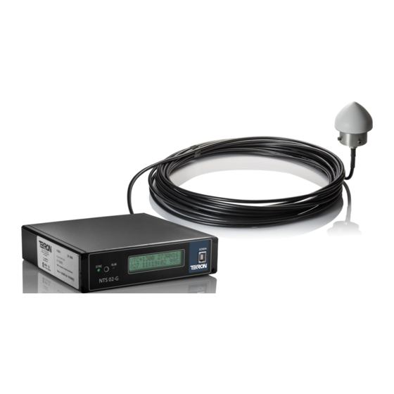
The NTS 02-G product is ideally suited for use in industrial environments and can provide NTP or PTP server functions to multiple independent Ethernet networks. All NTS 02-G units feature a front panel display (see Figure 1) giving visual feedback about the time data being generated on the outputs. LED indicators provide “at a glance” status information. -
Page 5: Front Panel
2. Front Panel Figure 2 – NTS 02-G front panel The NTS 02-G features two LED indicators on the front panel (see Figure 2), together with a USB port and a 2-line by 16-character backlit LCD display. SYNC LED: This LED shows the current sync status of the NTS 02-G. - Page 6 The display screens in Figure 3b, 3c, 3d and 3e, each show a three-character status field at the bottom right-hand corner of the display. When the NTS 02-G is operating in its default mode as a GNSS synchronized grandmaster, this field provides further details about the GNSS function as shown in Figure 4a and Table 1a below.
- Page 7 When the NTS 02-G is synchronized from an IRIG-B source, this field directly indicates the sync source. (See example for “SLC” source in Figure 4b). Table 1b shows the alternate sync sources supported by the NTS 02-G. LST: TUE 17MAR13...
-
Page 8: Contrast Adjustment Mode
Fast Flash (5 flashes per second): The NTS 02-G is not synchronized. “Out of Sync” condition The ALM LED indicates the internal alarm status of the NTS 02-G. It has only two operating states: - Off: The NTS 02-G is operating normally, i.e., there are no alarms. - Page 9 The number of satellites currently being used for time and position calculations is below the threshold. Sync No Sync The NTS 02-G is not synchronized to any source, or holdover period has expired, or the timing output inaccuracy has been exceeded. Hold Holdover The NTS 02-G has lost synchronization to any source and is now in holdover.
-
Page 10: Usb Port
Admin Ethernet port 1. The configuration software supplied with the NTS 02-G supports both USB and Ethernet configuration. A USB driver for the NTS 02-G can be downloaded from www.support.tekron.com. The NTS 02-G can be configured through the USB admin port only, to add an extra security layer. -
Page 11: Back Panel
3. Back Panel Examples of the NTS 02-G back panel are shown below (see figures 6 and 7). The unit appearance varies depending on the types of Ethernet modules fitted (orderable factory options). Figure 6 – Rear panel of NTS 02-G with copper outputs P1 Power Input Power is applied to the NTS 02-G via P1, a 5.08 mm 3-pin connector. -
Page 12: Antenna Cable Considerations
Antenna Cable Considerations The NTS 02-G antenna port expects a signal with a gain of at least 15 dB, and no more than 35 dB, with 20 - 35 dB being the optimal gain range. All antenna cables will introduce some signal loss in the antenna installation system, which will be dependent on cable length. -
Page 13: P2: Irig-B Input (3-Pin 3.81 Mm Connector)
*Note: When no extensions are contained in the incoming IRIG-B signal, the incoming time is assumed to be UTC. When configured appropriately, the NTS 02-G can synchronize to this source rather than the internal GNSS receiver, operating as a slaved device from another master source or other time server. -
Page 14: P4: Sync And Antenna Alarm Relays (4-Pin 3.81 Mm Connector)
The NTS 02-G operates with the alarm relays energized during normal operation, and de- energized in the alarm state. It follows that, in the event of all power to the NTS 02-G being lost, both alarm relays default to the “alarm” state (open contact). The “+” and “-” symbols are included for reference purposes only, as the alarm contacts are not polarized. -
Page 15: Software
4. Software Configuration Tool The NTS 02-G can be configured via USB or Ethernet. The configuration tool can be downloaded from the Tekron Support Website: www.support.tekon.com. By default, the unit is shipped with DHCP enabled for automatic IP address assignment, with a fall back to link local addressing (169.254.xxx.xxx) if no DHCP server is present. -
Page 16: Installation
5. Installation Identification Each NTS 02-G unit is shipped with identification labels on the base and side of the unit. The labels provide details on the hardware options fitted in the unit during manufacture, as well as the power supply requirements and the unit serial number. -
Page 17: Mounting The Nts 02-G
Mounting the NTS 02-G The NTS 02-G can be used free-standing or mounted in a 19” rack. Each unit ships with a rack-mount bracket which can be attached by removing the 4 corner front panel screws and attaching the plate as illustrated in Figure 7 . -
Page 18: Factory Reset
6. Factory Reset The NTS 02-G features the ability to reset to factory default settings in the event that the administrator password is forgotten, or if the time server is rendered unreachable on the network due to incorrect settings, provided that physical access to the unit is available. -
Page 19: Factory Hardware Options
Slave Only Option (Fiber input) The NTS 02-G can be ordered as a slave-only device in which case, the SMA antenna jack is removed, and an ST Fiber receiver port (multi-mode) is fitted instead. The unit will synchronize to an incoming IRIG-B signal on either P2 (RS422 format signal required) or on the Fiber input. -
Page 20: Appendix
8. Appendix NTS 02-G Specifications Physical Specifications Width 160 mm Dimensions Depth 155 mm Height 40 mm Weight 800 g Operating Temperature Range -10 to +65 Storage Temperature Range -40 to +85 Operating Humidity 10 ~ 95 % non-condensing Electrical Specifications... - Page 21 GNSS Receiver L1/GLONASS (1575.42 / 1598-1606 MHz) Frequency, C/A Code, 32 Channel, parallel-tracking receiver Position Horizontal <9 m (90%) Accuracy Altitude <18 m (90%) Timing Accuracy <15 ns (1 sigma) to UTC Acquisition -148 dBm Sensitivity Tracking -160 dBm Antenna output voltage Antenna output current 100 mA (max) 21 |...
-
Page 22: Warranty Statement
Copyright ©2014 Tekron International Ltd. All rights reserved. No part of the contents of this document may be transmitted or reproduced in any form or by any means without the written permission of Tekron International Ltd. Published in New Zealand.
Need help?
Do you have a question about the NTS 02-G and is the answer not in the manual?
Questions and answers