Table of Contents
Advertisement
FPD
F
D1M
Di
igital Fl
lat Pane
U
ser M
Manua
AD
DDRESS:2F,
Building 7, N
Zhangjiang Ea
Z
S
hanghai, Chin
PO
OSTALCODE:
201201
M
(Br
and nam
el Detec
ctor
al
iRay
y Techno
ology(Sh
No. 590, Ruiq
qing Road,
ast, Pudong N
New Area,
na
me:Ven
nu1717M
hanghai)
Ltd.
TEL:+8
6‐21‐507205
FAX:+8
86‐21‐507205
DATE: 20
011‐05
003‐202‐0
2 A5
M)
560
561
Advertisement
Table of Contents

Subscribe to Our Youtube Channel
Related Manuals for iRay Technology Venu1717M

Summary of Contents for iRay Technology Venu1717M
- Page 1 003‐202‐0 2 A5 and nam me:Ven nu1717M igital Fl lat Pane el Detec ctor ser M Manua iRay y Techno ology(Sh hanghai) Ltd. DDRESS:2F, Building 7, N No. 590, Ruiq qing Road, TEL:+8 6‐21‐507205 560 Zhangjiang Ea ast, Pudong N New Area, FAX:+8 86‐21‐507205 561 hanghai, Chin na DATE: 20 011‐05 OSTALCODE:...
-
Page 2: To Customers
003‐202‐02 A5 To customers Trademarks The iRay name and iRay logo are registered trademarks of Shanghai iRay Technology Ltd. (Hereinafter referred to as iRay) Copyright All rights reserved. Under copyright laws, this manual may not be reproduced, in whole or in part, without the written permission of iRay. - Page 3 003‐202‐02 A5 9. To pull out the plug is the only way to cut down the main power supply. 10. Prevent the detectors from sharp/hard things, or the cover will be broken. If the painting or the cover is broken, do not contact with surface directly. Disclaimer 1.
-
Page 4: Note On Installation
003‐202‐02 A5 Note on installation Request your sales representative or local iRay dealer to install this product. Note on disposal of this product Disposal of this product in an unlawful manner may have a negative impact on health and on the environment. When disposing of this product, therefore, be absolutely sure to follow the procedure which is in conformity with the laws and regulations applicable in your area. - Page 5 003‐202‐02 A5 warranty. Client must offer product’s serial number. Under warranty, some damages don’t need take any service expense and components expense because of unartificial factors. Under warranty, some damages only need take components expense and need not take any service expense because of artificialness.
- Page 6 003‐202‐02 A5 Symbol for “the name and the address of the manufacturer” Symbol for “The name and the address of the authorized representative in the European Community” Symbol for “consult instructions for use”, “consult operating instructions”. Safety Signs: Symbol for “refer to instruction manual” Safety Signs:Symbol for “Dangerous Voltage”...
- Page 7 003‐202‐02 A5 Symbol for “The equipment shall be operated during the upper and lower limits of temperature” Package symbol, symbol for “Fragile, the package should be handledwith care” Package symbol, symbol for “Keep awayfrom sunlight” Package symbol, symbol for “Keep dry” Package symbol, symbol for “The humidity limitationshall be indicated adjacentto the upper horizontal lines”...
-
Page 8: Table Of Contents
003‐202‐02 A5 Contents TO CUSTOMERS ..........................1 NOTE ON INSTALLATION ......................... 3 ABOUT SERVICE INFORMATION ....................3 SAFETY NOTICES ..........................9 1. SAFETY INFORMATION ......................10 2. GENERAL DESCRIPTION ......................18 2.1 S ............................18 COPE 2.2M ............................19 ODEL 2.3 C .......................... - Page 9 003‐202‐02 A5 APPENDIX F INFORMATION OF MANUFACTURE ..............64 APPENDIX G INFORMATION OF SERVICE OFFICE ..............65 8 / 66 ...
-
Page 10: Safety Notices
003‐202‐02 A5 Safety notices The following safety notices are used to emphasize certain safety instructions. This manual uses the caution symbol along with a caution message. This notice is used to identify conditions under which improper use of the product may cause death or serious personal injury. This notice is used to identify conditions under which improper use of the product may cause minor personal injury. -
Page 11: Safety Information
1. Safety Information 1. Safety Information 1.1 Safety precautions Follow these safeguards and properly use the equipment to prevent injury and damage to any equipment/data. WARNING Installation and environment of use Do not use or store the equipment near flammable chemicals such as alcohol, thinner, benzene, etc. - Page 12 1. Safety Information Not doing so may result in fire or electric shock. Securely plug the power cord into the AC outlet. If contact failure occurs, or if metal objects come into contact with the exposed metal prongs of the plug, fire or electric shock may result. ...
- Page 13 1. Safety Information WARNING Handling Never disassemble or modify the equipment. No modification of this equipment is allowed. Doing so may result in fried or electric shock. Also, since the equipment incorporates parts that may cause electric shock as well as other hazardous parts,touching them may cause death or serious injury.
- Page 14 1. Safety Information CAUTION Installation and environment of use Do not install the equipment in any of the locations listed below. Doing so may result in failure or malfunction, equipment falling, or fire or injury. Close to facilities where water is used ...
- Page 15 1. Safety Information CAUTION Handling Handle the equipment carefully. Do not submerge the equipment in water. The internal image sensor may be damaged if something hits against it, or if it is dropped, the drop sensor will turn red and the equipment will not be warranted by iRay.
- Page 16 1. Safety Information 1.2 Notes for using the equipment When using the equipment, take the following precautions. Otherwise, problems may occur and the equipment may not function correctly. Before exposure Be sure to check the equipment daily and confirm that it works properly. ...
- Page 17 1. S afety Informa ation Do no ot spray the e detector di irectly with disinfectan nts or deterg gents. Wipe the detecto or using a c cloth wetted d with neu tral deterge ent. Do not t use solven nts such as alcohol, th...
- Page 18 1. Safety Informa ation 17 / 66 ...
-
Page 19: General Description
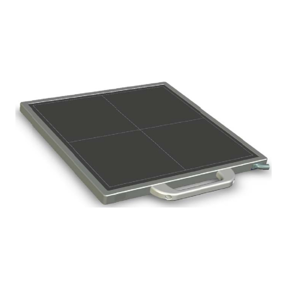
2. General Description 2. General Description ® FPD1M is an advanced digital radiographic flat panel detector based on amorphous silicon thin-film transistor technologies.FPD1M is a member of iRay’s detector family for static x-ray imaging. FPD1M is designed to provide the highest quality of radiographic image. -
Page 20: M Odel
2. Ge eneral Descri iption 2Model Active area Pixel Size Model Brand Na Type of Use Pixel matri m) (cm ) (μm FPD1M Venu1717 42.7×42.7 3072×307 Move eable 3 Charac cteristic Fixed stati c Flat Pane l Detector u used for gen neral radiog raphy. -
Page 21: Standard Configuration
2. General Description iRay will provide detector and software support for integration of system. For Distributor iRay will provide detector and software support for upgrading of system. 2.5 Standard configuration The FPD1M detector comes with a power supply which connects to 110-240 AC outlet and generates DC voltages needed by the detector. -
Page 22: Main Specifications
2. General Description 2.6Main Specifications 2.6.1 Useful entrance field size All the FPD detectors should meet the following requirements, the useful entrance field size should be more than 95% nominal entrance field size. Entrance field size Model Nominal entrance field size ( cm) Useful entrance field size(cm) FPD1M 43 ×... - Page 23 2. General Description 0.07 0.04 0.02 2.6.13 Detective quantum efficiency(DQE) The MTF should meet the following table Standard radiation quality No. Spatial frequency RQA/μGy (horizontal)or(vertical) 0.15 5/2.5 0.05 0.02 0.01 2.6.14 Lag effect should be less than 0.5%。 2.6.15 Multiplicative lag effect should be less than 0.5%。 2.6.16 FPD1M effective area, pixel matrix and pixel dimension Effective area pixel dimension...
- Page 24 2. General Description Item Control Box: (Control box is specified as a part of ME Equipment) FPD1M UART WIRE Extension Cable HVG Cable Ethernet Cable 23 / 66 ...
- Page 25 2. General Description Item Power Cable Fuse 2.8 Description of Indicators Indicator of Control box: Items Color Descriptions Power OFF Power Green(steady) Power supply is normal Indicators of detecter Items Color Descriptions Power OFF Power Green(steady) Power supply is normal Power OFF data Green(steady)
- Page 26 2. General Description 2.9 Image Direction Please notice that the image direction is defined as follows: 25 / 66 ...
-
Page 27: Installation And Operation
3. Installation and Operation 3. Installation and Operation The following is a general installation guide. The interface & operation may be different between different firmware and software editions. Please contact iRay service office for the details. Before installation, please check the MPN (Manufactory Product Number) of the equipment cable and the version of the control box. -
Page 28: Q Uick Start
3. Insta llation and O Operation 1Quick S Start fore using the detecto or, user m ust read th he appendi ix A for d details of S ® inst allation. Th hen user can n use the Qu uick Start so oftware iSta for ima age acquisit... - Page 29 3. Insta llation and O Operation As s shown in th he above fig gure, on the right there are 5 class’s s buttons. Control cla ass: “Start” ” buttonto initialize th he Gigabit Ethernet d driver. The user needs to select the Gigabit E Ethernet ad...
- Page 30 3. Insta llation and O Operation 3 Mechan nical Dr rawing FPD1M de etector structu ure diagram PD1M contro l box structur re diagram 4 To acqu uire a no ormal cli inical di agnostic c image The clinica al diagnosti c image doe es not conta ain the defec...
- Page 31 3. Installation and Operation and any other image defect. Human tissue should be fit for the requirements of clinical diagnosis, the image should be clearly and identifiable. 30 / 66 ...
-
Page 32: Control Box Interface
4. C Control Interf face Contr rol Bo ox Inte erface ntrol box wh hich is regar rded as is the e relay devic a par rt of medical e electrical equi ipment betw ween compu uter and det tector. All th he plug and d connector should be p... - Page 33 4. C Control Interf face age acquisit tion and co onfiguration n command ds from th he user’s co omputer to o the dete ector. If th he pc does not have a standard s erial port, t the user can nuse usb- -serial conv...
-
Page 34: Gigabit Ethernet Port
4. Control Interface 4.3 Gigabit Ethernet Port The GBE port shall be connected with an Ethernet cable to a Gigabit Ethernet Port of the user’s computer. The GBE port transmits image data through Gigabit Ethernet protocol. For NIC (Network Interface Card), Intel Pro EXP9301CT PROGigabit Network Adapter with PCIe interface is recommended. -
Page 35: Inner Digital Sync-Shot Module
4. Control Interface 4.5 Inner Digital sync-shot Module The detector has an embedded well-proved module with Ionization Chamber sync-shot board for automatic exposure control. The module can provides sync-shot sync-shot a very stable inner trigger signal of calibrated pulses with a resolution of up to 5nGy.The energy range is from 40kV to 150kV. - Page 36 4. Control Interface Soft-trigger mode Software command Acqu Event (A-EVENT) When acqu event occur, detector will start progressive scanning and acquisition the image of TFT matrix sensor. In addition, use can adjust the acqu event delay time for some requirements. Applied Trigger Mode Trigger Method Outer-trigger mode...
- Page 37 4. Control Interface software can get this value then invoke the PA-EVENT for precise post-offset. 36 / 66 ...
-
Page 38: Regulatory Information
5. Regulatory Information 5. Regulatory Information The product safety standards that apply to the FPD1M, which includes the main unit detector and power adaptor. 5.1 Medical equipment safety standards Medical equipment classification Type of protection against electrical shock Internally powered equipment Class I Equipment, with wiring unit Degree of protection against electrical shock Type B Applied Parts... -
Page 39: Guidance And Manufacture's Declaration For Emc
5. Regulatory Information Medical electrical equipment-Part 2-54: Particular requirements EN 60601-2-54 for the basic safety and essential performance of X-ray equipment for radiography and radioscopy Medical electrical equipment-Characteristics of digital X-ray EN 62220-1 imaging devices- Part 1: Determination of the detective quantum efficiency EN 62304 Medical device software - Software life-cycle processes... - Page 40 5. Regulatory Information Floors should be wood, concrete or Electrostatic discharge ±6 kV contact ±6)kV contact ceramic tile. If floors are covered (ESD) ±8)kV air ±8kV air with synthetic material, the relative IEC 61000-4-2 humidity should be at least 30%. ±2 kV for power ±2 kV for power Electrical fast transient/...
- Page 41 5. Regulatory Information where P is the maximum output power rating of thetransmitter in watts according transmittermanufacturer and d is the recommended separationdistance in metres (m). Field strengths from fixed transmitters, as determinedby an electromagnetic site survey,a should beless than the compliance level in each frequencyrange.
- Page 42 5. Regulatory Information FPD1M detector can help prevent electromagnetic interference by maintaining a minimum distance between portable and mobile RF communications equipment (transmitters) and the FPD1M detector as recommended below, according to the maximum output power of the communications equipment. Rated maximum Separation distance according to frequency of transmitter /m output...
- Page 43 5. Regulatory Information Important information regarding Electro Magnetic Compatibility (EMC) The FPD1M detector needs special precautions regarding EMC and needs to be installed only by iRay or authorization engineer and put into service according to the EMC information provided in the user manual; The FPD1M detector in use may be susceptible to electromagnetic interference from portable and mobile RF communications such as mobile (cellular) telephones.
- Page 44 5. Regulatory Information b) The Interface to HVG Cable should be winding more than 2 turns near the Interface port on the controlbox. c) If USB to RS232 cable were used, the cable should be winding more than 2 turns near the USB port.
-
Page 45: Imaging Software Sdk
6. Image Software SDK 6. Imaging Software SDK The imaging software library IrayAcquireLib.libprovides the fundamentalfunctionsfor detector configuration and image acquisition.A program iDemo has been included in the package to demonstrate how to use this library. Please note that the images acquired from the IrayAcquireLib.lib have only been modestly processed and the usersneed to develop their own software with a separate image processing engine. - Page 46 6. Image Software SDK Acquisition_SetImageCallback Set callback function of capturing image by Cameralink card object. Acquisition_SetComCallback Set callback function of uart settings. Acquisition_GigeGetAdapterList Get the network card list of PC. Acquisition_GigeFreeAdapterList Release the network card list of PC. Acquisition_GigeCreateAdapterObject Create the object of selected network card. Acquisition_GigeDeleteAdapterObject Release the object of selected network card.
-
Page 47: Description Of Function
6. Image Software SDK 6.2Description of Function: 6.2.1Acquisition_Initialize The function is initializing theuart device. The parameters of uart will be obtained by pCom. ACQUIRE_HEADER_API INT Acquisition_Initialize( PCHARpCom Description of parameters: pCom:The number of used uart port, such as com1. Return values: 1:Successful. - Page 48 6. Image Software SDK e.g. Acquisition_SetCommDCB("baud=9600 parity=N data=8 stop=1"); ACQUIRE_HEADER_API BOOL Acquisition_SetCommDCB( PCHAR strDCB Description of parameters: strDCB:Parameter of uart device. Return values: FALSE:Failed. TRUE:Successful. 6.2.5Acquisition_StartAcquisition The function is start acquisition one frame of image. When execute this function, one-frame-acquisition command will be sent by com port. Then thedetector will start scan and transfer image back.
- Page 49 6. Image Software SDK TRUE:Successful. 6.2.8 Acquisition_GetDRConfigVersion The function retrieves the firmware version. ACQUIRE_HEADER_API WORD Acquisition_GetDRConfigVersion( WORD &wV1, WORD &wV2, WORD &wV3 Description of parameters: wV1:Product No.. wV2:Release No.. wV3:Amendment No.. 6.2.9 Acquisition_StartAecReady The function is start SYNC-SHOT ready. When execute this function, one-frame-acquisition command will be sent by com port.
- Page 50 6. Image Software SDK Description of parameters: pAecInfo: The callback function of SYNC-SHOT. pUser:The pointer of user. 6.2.11Acquisition_SetImageCallback The function is set the callback function of acquisition image. The parameter pImageHandle is the function pointer of image information. When the user creates the global function to transfer the parameter pImageHandle, then this function is received by running library and registered.
- Page 51 6. Image Software SDK 6.2.13 GIGE_ADAPTERNAMELIST* Acquisition_GigeGetAdapterList(); The function is to return the pointer of structGIGE_ADAPTERNAMELIST. It is a one-way chained list, which has saved the name of network card. Return values: GIGE_ADAPTERNAMELIST:The header of chained list of network card name.
-
Page 52: Demo Illustration
6. Image Software SDK Return values: <0, means open failed. 6.2.17UINT Acquisition_GigeGetAdapterObjectSpeed( HANDLE pAdapter The function is used for test the speed of current linked network card. If the speed is lower than 1000M, means linking failed. Description of parameters: pAdapter:The handle of linked network card object. - Page 53 6. Image Software SDK 3).Return the connection information of NIC. Acquisition_GigeAdapterIsConnected(PCHAR pAdapterName,BOOL &bConnect) 4).Set the callback function of image acquisition. Acquisition_GigeAdapterObjectSetImageCallback(m_hGigeAdapter,pImag eCallback,pUser); 7).Set the callback function of Uart. Acquisition_SetComCallback(pStatusCallback, pUser); 2.Start acquisition the image 1).Acquisition the dark image. Acquisition_StartAcquisition(); 2).Acquisition the exposuring image. 3.Unload 1).Unload the network card Acquisition_GigeDeleteAdapterObject(m_hGigeAdapter);...
-
Page 54: Service Information
7. Service Information 7. Service Information Product lifetime The estimated product lifetime is up to 5 years under appropriate regular inspection and maintenance. Regular inspection and maintenance In order to ensure the safety of patients, operating personal and third parties, and to maintain the performance and reliability of the equipment, be sure to perform regular inspection at least once a year. - Page 55 7. Service Information Fig 7.1 Remove the fuse holder from the power filter c) Replace the fuse with a new one (Fig.7.2) d) Insert the fuse holder back into the power filter. Fig 7.2 Replace the fuse Trouble Shooting When you encounter problems or error message in using FPD1M detector, search the table below for the problem or error message and try the solutions.
- Page 56 7. Service Information Consult iRay’s or iRay’s authorized Filed Application Engineer. Link lamp does not communication Check the LAN cable whether loose, light up circuit is not secured. plug the LAN cable again. Consult iRay’s or iRay’s authorized Filed Application Engineer. Power lamp does not The power circuit is not Check the power supply connector and...
-
Page 57: Appendix A Installation Of Sdk
Appendix x A Installatio on of SDK ppend dix A I nstalla ation o of SDK e detector pr rovides two o interfaces f for image a acquisition. For using, u user must inst all the relat tive softwar re rightly. - Page 58 Appendix x A Installatio on of SDK Do not sele ect the “Au utomatically y start the W WinPcap driv ver at boot t time” item. function w will be loade ed by theima age acquisit tion softwar Then instal llation comp pleted When...
- Page 59 Appendix x A Installatio on of SDK 58 / 66 ...
- Page 60 Appendix B FPD1M Dummy Lines Appendix B FPD1M Dummy Lines There are 8 dummy lines on the each long edge of the image. Fig D1 59 / 66 ...
- Page 61 Appendix B FPD1M Dummy Lines In details Fig D2 60 / 66 ...
-
Page 62: Appendix C Function List Of Different Hardware/Firmware Versions
Appendix C Function List of Different Hardware/Firmware Versions Appendix C Function List of Different Hardware/Firmware Versions Detector Firmware Function 1. RS232 command interface main board: 3.3.18 2. Static image acquisition read board : 3.1.5 3. Gigabit Ethernet command interface 4. -
Page 63: Appendix D Recommended Computer Platform
Appendix D Recommended Computer Platform Appendix D Recommended Computer Platform Recommended Recommended Minimum Desktop Laptop Intel Core i3 2.8G Intel Core i73.6G Intel Core i73.6G Memory 2G DDR3 4G DDR3 4G DDR3 Hard Disk 160 G 640 G 320 G Monitor 1280×1024 1680 x 1050... - Page 64 Appendix E Definition of Defects Appendix E Definition of Defects Defect Pixel: A defect pixel is defined as a pixel whose value is deviated from the median of its neighboring 32x32 pixels by more than 6 times of the standard deviation of this regionafter gain-offset correctionunder any X ray condition.
- Page 65 Appendix F Information of Manufacture Appendix F Information of Manufacture Shanghai iRay Technology Ltd. Rm202, Building 7, No. 590, Ruiqing Rd, Zhangjiang East, Pudong New Area, Shanghai, China POSTCODE: 201201 TELEPHONE: +86-21-50720560 FAX: +86-21-50720561 HOMEPAGE: WWW.IRAY-TECH.COM SERVICE: SERVICE DEPARTMENT of iRay...
- Page 66 Appendix G Information of Service Office Appendix G Information of Service Office Tel: +86 21 50720560 - 8059 Fax: +86 21 50720561 E-mail: service@iraychina.com Address: 2F, Building 7, No.590, Ruiqing Rd, Pudong, Shanghai, China PC: 201201 65 / 66 ...
Need help?
Do you have a question about the Venu1717M and is the answer not in the manual?
Questions and answers