Table of Contents
Advertisement
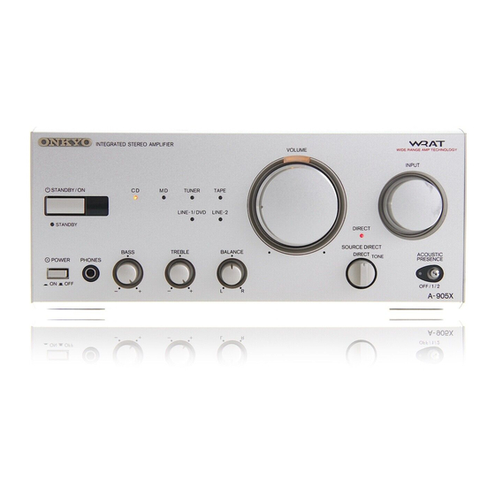
Integrated Stereo Amplifier
A-905X
STANDBY/ON
STANDBY
POWER
ON
OFF
Instruction Manual
INTEGRATED STEREO AMPLIFIER
CD
MD
TUNER
TAPE
LINE-1/ DVD
LINE-2
BASS
TREBLE
BALANCE
PHONES
−
+
−
+
L
R
VOLUME
WIDE RANGE AMP TECHNOLOGY
INPUT
DIRECT
SOURCE DIRECT
DIRECT
ACOUSTIC
PRESENCE
TONE
OFF/1/2
A-905X
English
Advertisement
Table of Contents

Related Manuals for Onkyo pmn


Summary of Contents for Onkyo pmn
- Page 1 Integrated Stereo Amplifier A-905X Instruction Manual INTEGRATED STEREO AMPLIFIER STANDBY/ON STANDBY BASS PHONES POWER − VOLUME TUNER TAPE LINE-1/ DVD LINE-2 DIRECT SOURCE DIRECT TREBLE BALANCE DIRECT + − + English WIDE RANGE AMP TECHNOLOGY INPUT ACOUSTIC PRESENCE TONE OFF/1/2...
-
Page 2: Before Using
Before using Thank you for purchasing ... Thank you for purchasing the ONKYO A-905X Integrated Stereo Amplifier. Please read this manual thoroughly before making any connection or turning on the power. Follow these instructions to obtain optimum performance and maximum listening enjoyment from your new A-905X. -
Page 3: Important Safeguards
Important Safeguards Read Instructions – All the safety and operating instructions should be read before the appliance is operated. Retain Instructions – The safety and operating instructions should be retained for future reference. Heed Warnings – All warnings on the appliance and in the operating instructions should be adhered to. - Page 4 ELECTRONICS GmbH INDUSTRIESTRASSE 20 82110 GERMERING, GERMANY declare in own responsibility, that the ONKYO product described in this instruction manual is in compliance with the corresponding technical standards such as EN60065, EN55013, EN55020 and EN61000-3-2, -3-3 (or EN60555-2, -3) GERMERING, GERMANY...
-
Page 5: Table Of Contents
Table of contents Connections Connecting to the ONKYO Separate Collection Series components ... 6 Connecting to components other than the Separate Collection Series ... 11 Connecting speaker systems ... 14 Connecting the AC power cord (mains lead) ... 16 Preparations Preparing the remote controller ... -
Page 6: Connections
Connections Connecting to the ONKYO Separate Collection Series components This section introduces you to the other Separate Collection Series system components and their con- venient system functions, followed by connecting instructions. The following Separate Collection Series components are commercially available: •... - Page 7 Arranging the system components Combination example 1 Select the tuner T-405X, CD player C-705X (or CD changer C-707CH), and stereo cassette tape deck K- 505X in addition to this unit. When you arrange these components, stack them as shown below. Vertical way stacking Tuner (T-405X)
- Page 8 Connecting to the ONKYO Separate Collection Series components Connecting to the audio connector Before connecting • Do not connect the unit’s AC power cord (mains lead) to a wall outlet (the mains) until you have completed all the other connections, including “Connecting to components other than the Separate Collection Series”...
- Page 9 50Hz UNSWITCHED100W MAX. TUNER ANALOG REMOTE INPUT OUTPUT CONTROL (REC) (PLAY) MD recorder (MD-105X) Optical cable OUT(REC) IN(PLAY) SPEAKERS INTEGRATED STEREO AMPLIFIER MODEL NO. RATING; REMOTE LINE-2 LINE-1 TAPE CONTROL OUT(REC) IN(PLAY) TUNER SUBWOOFER PROCESSOR PRE OUT IN(PLAY) Amplifier – this unit (A-905X)
- Page 10 Connecting to the ONKYO Separate Collection Series components Connecting the Before connecting • The hookups on page 8 or 9 are needed in addition to the OUTLET (for power supply to each component) hookups on this page. • Each component has two components may be connected in any order.
-
Page 11: Connecting To Components Other Than The Separate Collection Series
To R connector Improper connection Insert completely Stereo cassette tape deck PLAY INPUT OUTPUT Amplifier – this unit (A-905X) OUT(REC) IN(PLAY) SPEAKERS INTEGRATED STEREO AMPLIFIER A-905X MODEL NO. RATING; REMOTE LINE-2 LINE-1 TAPE CONTROL OUT(REC) IN(PLAY) AC OUTLET AC230V 50Hz... - Page 12 REMOTE LINE-2 LINE-1 TAPE CONTROL OUT(REC) IN(PLAY) TUNER SUBWOOFER PROCESSOR PRE OUT TUNER : Signal flow Jumper plug INTEGRATED STEREO AMPLIFIER MODEL NO. A-905X RATING; AC OUTLET AC230V 50Hz SWITCHED 100W MAX. OUT(REC) IN(PLAY) SUBWOOFER PROCESSOR PRE OUT INPUT Sound processor...
-
Page 13: Connecting The Cables
Connecting the cables If your other components are made by ONKYO and those components are equipped with tors, you can control the -connected components with the supplied remote controller. Before connecting • The unit must be connected in the • Each component has two •... -
Page 14: Connecting Speaker Systems
SPEAKERS Note To prevent damage to circuits never short-circuit the positive (+) and negative (–) speaker wires. Left speaker SPEAKERS INTEGRATED STEREO AMPLIFIER MODEL NO. A-905X RATING; REMOTE CONTROL IN(PLAY) AC OUTLET AC230V 50Hz This unit SUBWOOFER... - Page 15 • The SUBWOOFER PRE OUT connector supplies the left and right mixed monaural signals to the sub- woofer. Connections This unit OUT(REC) IN(PLAY) SPEAKERS INTEGRATED STEREO AMPLIFIER MODEL NO. A-905X RATING; REMOTE LINE-2 LINE-1 TAPE CONTROL...
-
Page 16: Connecting The Ac Power Cord (Mains Lead)
Connecting the AC power cord (mains lead) INTEGRATED STEREO AMPLIFIER TUNER TAPE STANDBY/ON LINE-1/ DVD LINE-2 STANDBY BASS TREBLE BALANCE POWER PHONES − + − + POWER switch STANDBY indicator Connect the AC power cord (mains lead) to the wall outlet (the mains). -
Page 17: Preparations
Preparations Preparing the remote controller Installing the remote controller batteries Remove the battery compartment cover by pressing the tab and lift- ing up the cover. Insert two AA (R6 or UM-3)-size batteries into the battery com- partment. Carefully follow the polarity diagram (posi- tive + and negative - symbols) inside the battery compartment. -
Page 18: Operation
Operation Turning the unit on INTEGRATED STEREO AMPLIFIER TUNER TAPE STANDBY/ON LINE-1/ DVD LINE-2 STANDBY BASS TREBLE BALANCE POWER PHONES − + − + STANDBY/ON STANDBY indicator Before turning the unit on Turn VOLUME control to the leftmost position to avoid damaging the speakers. -
Page 19: Choosing The Required Source
Choosing the required source Input source indicators INTEGRATED STEREO AMPLIFIER VOLUME TUNER TAPE STANDBY/ON LINE-1/ DVD LINE-2 STANDBY BASS TREBLE BALANCE POWER PHONES − + − + Turn INPUT selector clockwise or counterclockwise until the input indicator of the source you wish to listen to lights. -
Page 20: Adjusting The Sound
Adjusting the sound INTEGRATED STEREO AMPLIFIER TUNER TAPE STANDBY/ON LINE-1/ DVD LINE-2 STANDBY BASS TREBLE BALANCE POWER PHONES − + − + BASS BALANCE TREBLE Adjust left and right speaker bal- ance. Turn BALANCE control to “L” to lower the volume level of the right speaker, or “R”... -
Page 21: Muting/Listening Through The Headphones
Muting/Listening through the headphones INTEGRATED STEREO AMPLIFIER VOLUME TUNER TAPE STANDBY/ON LINE-1/ DVD LINE-2 STANDBY BASS TREBLE BALANCE PHONES POWER − + − + PHONES TONE: You can adjust the tonal quality of the signal selected by the Input Selector us- ing the BASS, TREBLE, and BALANCE controls. -
Page 22: Recording
1 Insert an MD into the MD recorder. e.g. 2 Insert a cassette into the stereo cas- sette tape deck. Start recording with the compo- nent prepared in step 3, then start playing the source prepared in step 2. ONKYO... -
Page 23: Other Information Troubleshooting
Other Information Troubleshooting If you have any problems with the unit, please check the troubleshooting table below first. For any problems not covered in the table, please consult your nearest ONKYO authorized service center. Cause Symptom The AC power cord is not fully in- The unit doesn’t turn on. -
Page 24: Specifications
Specifications Power output 15 watts per channel, min RMS, at 8 ohms, both channels driven 1 kHz, with no more than 0.2% THD 20 watts at 4 ohms, 1 kHz (DIN) 15 watts at 8 ohms, 1 kHz (DIN) Total harmonic distortion 0.2% at rated power IM distortion 0.2% at rated power... -
Page 25: Index To Parts And Controls
STEREO AMPLIFIER MODEL NO. RATING; REMOTE CONTROL OUT(REC) IN(PLAY) SUBWOOFER PROCESSOR PRE OUT MD OUTPUT (REC)/INPUT (PLAY) jacks [8, 11] Power/muting lamp [18, 21] INTEGRATED STEREO AMPLIFIER VOLUME TUNER TAPE LINE-1/ DVD LINE-2 BASS TREBLE BALANCE − + − + BALANCE... -
Page 26: Input Selector
Index to parts and controls Remote control – The unit operation buttons POWER button [18] POWER INPUT SELECTOR ACOUSTIC G.EQUALIZER CLOCK CALL SLEEP PRESENCE EFFECT MODE TUNER TAPE PRESET PAUSE/STEP REPEAT SCROLL PLAY MODE CLEAR REPEAT RANDOM MEMORY CLEAR DISC CD/MD TIMER UP/DOWN... - Page 27 Remote control – Operating buttons for other components • You can control the other • The remote controller buttons operate in the same way as the buttons on each component with the same indication. • For actual operations, please refer to the Instruction Manual for each component. •...
- Page 28 18 Park Way, Upper Saddle River, N.J. 07458, U.S.A. Tel: 201-785-2600 Fax: 201-785-2650 http://www.onkyousa.com ONKYO EUROPE ELECTRONICS GmbH Liegnitzerstrasse 6, 82194 Groebenzell, GERMANY Tel: 49-8142-4401-0 Fax: 49-8142-4401-555 http://www.onkyo.net ONKYO CHINA LIMITED Units 2102-2107, Metroplaza Tower I, 223 Hing Fong Road, Kwai Chung, HOMEPAGE N.T., HONG KONG Tel: 852 2429 3118 Fax: 852 2428 9039...
Need help?
Do you have a question about the pmn and is the answer not in the manual?
Questions and answers