
Subscribe to Our Youtube Channel
Related Manuals for OptoTest OP721


Summary of Contents for OptoTest OP721
- Page 1 OP721 Bidirectional Optical Switch Instruction Manual www.optotest.com 1.805.987.1700...
- Page 2 The design concepts and engineering details embodied in this manual, which are the property of OptoTest Corporation, are to be maintained in strict confidence. No element or detail of this manual is to be spuriously used or disclosed without the express written permission of OptoTest Corporation.
-
Page 3: Table Of Contents
OP721 Table of Contents Overview Features Initial Preparation Front Panel Operation & Display Example Instrument Setup Internal Switch Diagram Bar State Cross State USB Control of the OP721 Warranty Information 2 of 8... -
Page 4: Overview
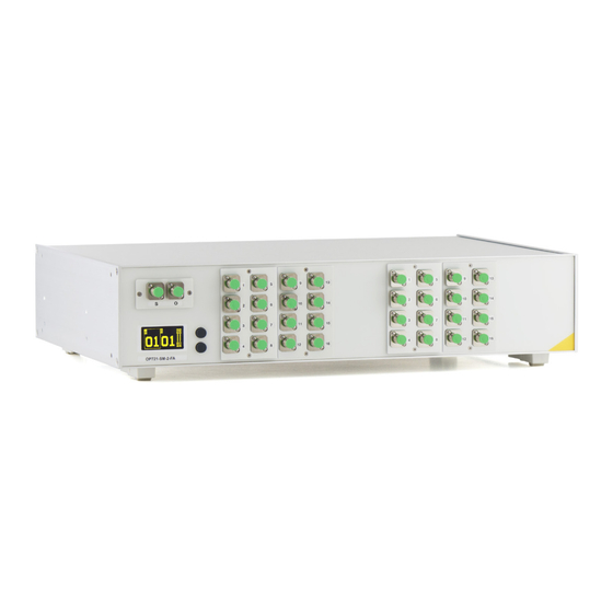
OP721 Overview The OP721 is an all-in-one bidirectional optical switch for single mode and multimode applications. This optical switch is powered by an external 5V power supply and incorporates the latest in high-speed switching technology. By combining the high channel count capability of the OP720 with the 2x2 configuration of the OP725, the OP721 is ideally suited for multifiber bidirectional testing. -
Page 5: Initial Preparation
Please retain the shipping container in case re-shipment is required for any reason. Damaged In Shipment All instruments are shipped F.O.B. Camarillo when ordered from OptoTest. If you receive a damaged instrument you should: 1. Report the damage to your shipper immediately. -
Page 6: Front Panel Operation & Display
OP721 Front Panel Operation & Display All functionality of the front panel is visible and adjustable from the modular home screen. The top button toggles between the different sections of the home screen, and the bottom button toggles options on the active section. A border around a section of the screen signifies that the section is active and can be changed. -
Page 7: Example Instrument Setup
OP721 Example Instrument Setup Internal Switch Diagram 6 of 8... -
Page 8: Bar State
OP721 Internal Switch Diagram Bar State light path and direction Cross State 7 of 8... -
Page 9: Usb Control Of The Op721
OP721 USB Control of the OP721 The OP721 can be controlled through the USB bus via OPL-MAX software and DLLs. Upon request, OptoTest can supply the appropriate DLLs along with sample programs to facilitate the software creation process. For these DLLs please contact sales@optotest.com. - Page 10 1.805.987.1700...
Need help?
Do you have a question about the OP721 and is the answer not in the manual?
Questions and answers