
Related Manuals for ENTRYPASS EP.HIO

Summary of Contents for ENTRYPASS EP.HIO
- Page 1 EP.HIO WIRING GUIDE Version: 1.04 Last Updated: 23-06-2016 ENTRYPASS TECHNICAL – WIRING GUIDE Copyright © Entrypass Corporation...
- Page 2 For existing site, P1 will detect its card database to determine 6 or 10 digits; For new site, user can change the digits as long as the card database is empty Please refer to separate EntryPass Platform1 User Manual for detail operation help. The Official EntryPass Platform1 User Manual can be downloaded from our website under “Download”...
-
Page 3: Before You Begin
Should you need additional information, please call our Technical Support Help desk, Monday to Friday 9:00 AM to 6:00 PM (GMT +8:00) Method Details Phone + 60 (3) - 8068 1929 Fax + 60 (3) - 8068 1922 Internet www.entrypass.net Email support@entrypass.net ENTRYPASS TECHNICAL – WIRING GUIDE Copyright © Entrypass Corporation... -
Page 4: Considerations Prior To Installation
Considerations Prior to Installation Preparing Your EntryPass Controllers EntryPass controller contains numerous delicate electronic circuits and components which can become damaged as a result of electrostatic discharge (ESD). Thus, prior to installation, please follow the instruction below: •Observe precautions while handling the circuit board assembly by using proper grounding straps and handling precautions at all •Visually ensure no onboard parts is broken, damage or contains burn mark... -
Page 5: Components Description
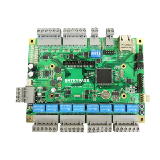
IDE Connector For Power Connector For Daughter Board Expansion Daughter Board Expansion 32-Bits Processor Power Connector Backup Battery Cold Start Button Onboard Power LED (5V and 3.3V) Reset Button Digital Output Connecter ENTRYPASS TECHNICAL – WIRING GUIDE Copyright © Entrypass Corporation... - Page 6 Digital Output LED Digital Input LED Expansion Board Power Cables Digital Output Connecter With the expansion board attached to the HIO controller, the HIO now support 16 Digital Inputs and 16 Digital Outputs ENTRYPASS TECHNICAL – WIRING GUIDE Copyright © Entrypass Corporation...
- Page 7 Power Supply Unit Specification ENTRYPASS Power Supply Unit Specification: • Switching Power Supply • 12V DC • 3 Amp (Minimum) ENTRYPASS TECHNICAL – WIRING GUIDE Copyright © Entrypass Corporation...
- Page 8 1 HIO controller RS 232: 10 meter (Pc Communicator) EntryPass Platform1 Server Access Control System When in RS485 mode, a total of 16 sets HIO controllers can be connected to each bus/comport. ENTRYPASS TECHNICAL – WIRING GUIDE Copyright © Entrypass Corporation...
- Page 9 If more than 1 HIO controller is connected to the PCC, the dip switch must be configure according to the pattern shown above. The default dip switch configuration of the HIO controller is 1 (ON) ENTRYPASS TECHNICAL – WIRING GUIDE Copyright © Entrypass Corporation...
- Page 10 The distance from HIO controller to network switch should not more than 100 meter . Please ensure the jumper is inserted on JP1 3-4 for TCP/IP mode. ENTRYPASS TECHNICAL – WIRING GUIDE Copyright © Entrypass Corporation...
- Page 11 CM1 NO1 NC2 CM3 NO3 NC4 CM4 NO4 CM5 NO5 NC6 CM7 NO7 NC8 CM8 NO8 Output 1 Output 2 Output 3 Output 4 Output 5 Output 6 Output 7 Output 8 ENTRYPASS TECHNICAL – WIRING GUIDE Copyright © Entrypass Corporation...
- Page 12 The On-Board HIO is shipped in package with L3800 Is advisable to connect a resistor (100 Ohm) as terminator on last HIO Other HIO boards must loop from ON-board HIO C2+/C2- ENTRYPASS TECHNICAL – WIRING GUIDE Copyright © Entrypass Corporation...
- Page 13 If more than 1 HIO controller is connected to the L1000 controller, the dip switch must be configure according to the pattern shown above. The default dip switch configuration of the HIO controller is 1 (ON) ENTRYPASS TECHNICAL – WIRING GUIDE Copyright © Entrypass Corporation...
- Page 14 (NC) and this HIO output connection is connected to the Lift Controller (floor button location). Thus, 1 HIO (without expansion board) can control up to 8 floors (Due to the 8 outputs available) ENTRYPASS TECHNICAL – WIRING GUIDE Copyright © Entrypass Corporation...
- Page 15 (NC) and this HIO output connection is connected to the Lift Controller (floor button location). Thus, 1 HIO (with expansion board) can control up to 16 floors (Due to the 16 outputs available) ENTRYPASS TECHNICAL – WIRING GUIDE Copyright © Entrypass Corporation...
- Page 16 3. Press RESET Switch and Release RESET switch 4. Release COLD switches when all the inputs LED will turn to ‘Yellow’ 5. When the process is complete, all the inputs LED will turn OFF ENTRYPASS TECHNICAL – WIRING GUIDE Copyright © Entrypass Corporation...
- Page 17 5. When the process is complete, all the inputs LED will turn OFF Factory Default will change the IP Address back to 192.168.1.100, Server IP to 192.168.1.254 and Port to 2020 ENTRYPASS TECHNICAL – WIRING GUIDE Copyright © Entrypass Corporation...
-
Page 18: Termination Setting
RS 485: 1000 meter (Maximum) It is advisable to insert a resistor value of 100 ohm on the last HIO controller for termination purpose if installation involve long communication distance or multiple units of HIO ENTRYPASS TECHNICAL – WIRING GUIDE Copyright © Entrypass Corporation... -
Page 19: Cabling Information
1000m 22 AWG, 2 Pairs, Shielded (3000 ft) Network Switch to HIO Network 100m 24AWG, 4 Pairs (300 ft) HIO digital input contact Contact 100m 24 AWG, 1 Pairs (300 ft) ENTRYPASS TECHNICAL – WIRING GUIDE Copyright © Entrypass Corporation...
Need help?
Do you have a question about the EP.HIO and is the answer not in the manual?
Questions and answers