Table of Contents
Advertisement
Quick Links
Advertisement
Table of Contents

Subscribe to Our Youtube Channel
Related Manuals for Control Bionics NEURONODE PL-27-1000

Summary of Contents for Control Bionics NEURONODE PL-27-1000
- Page 1 NeuroNode USER GUIDE Client Support USA: (513) 453-4848 AUS: (03) 9897-3576...
- Page 2 This page is intentionally left blank. 20220225...
- Page 3 Powered Environmental Control System and certified by the Australian Government Depart- ment of Health Therapeutic Goods Administration. Copyright 2006 - 2022 Control Bionics Inc. All Rights Reserved. NeuroEDUCATOR® and NeuroNode® are trademarks of Control Bionics Inc. Anatomic images ©CLIPAREA l Custom media/Shutterstock.
- Page 4 Catalog Number: 27-3500 User Guide, Revision J This device complies with part 15 of the FCC Rules. Operation is subject to the following two conditions: (1) This device may not cause harmful interference, and (2) this device must accept any interference received, including interference that may cause undesired operation. NOTE: This equipment has been tested and found to comply with the limits for a Class B digital device, pursuant to part 15 of the FCC Rules.
- Page 5 Intended Purpose: NeuroNode is an Augmentative and Alternative Communication (AAC) device intended to provide noninvasive, electromyographic (EMG)-mediated computer access, communication, and environ- mental control capability for users with impaired speech and/or motor function. Other user actions and gestures (e.g. touch, visual, movement) can complement this EMG-based computer control. NeuroNode is non-sterile and reusable, and is intended to be used continuously for up to 24 hours in contact with the user’s intact muscle-contacting skin surface.
- Page 6 This page is intentionally left blank.
-
Page 7: Table Of Contents
PAGE 2 | CONTENTS Contents 1.0 Welcome to NeuroNode................2.0 Overview of NeuroNode................2.1 Overview of Accessories..............3.0 Getting Started....................3.1 NeuroNode EMG Placement............3.1.1 Connecting to the NeuroNode Using EMG....3.2 NeuroNode 3D Spatial Control............3.2.1 Connecting to the NeuroNode Using 3D Spatial..3.2.2 Advanced Menu.............. -
Page 8: Welcome To Neuronode
PAGE 3 | WELCOME TO NEURONODE 1.0 Welcome to NeuroNode The NeuroNode uses the body’s bioelectrical EMG (electromyography) signals or 3D Spatial awareness to give a user complete control of a computer to generate speech, browse the web, listen to music, and more. It is alternative/augmentative communication (AAC) technology that is easy to use and works for conditions like ALS, MND, SCI, or Cerebral Palsy. -
Page 9: Overview Of Neuronode
Signal Indicator This user guide reflects the current configuration of the NeuroNode. Previous versions of the NeuroNode may differ in the feature set, battery management, reset functions, and the behavior of the indicator lights. Contact Control Bionics for more information. -
Page 10: Overview Of Accessories
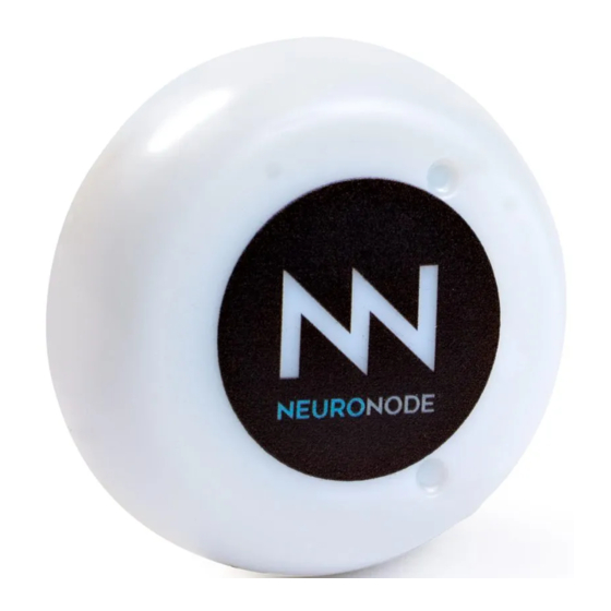
PAGE 5 | OVERVIEW OF NEURONODE 2.1 Overview of Accessories NeuroNode Leadwire Adapter Charger Kit Base NeuroNode Band Electrode Kit Item What It Does The NeuroNode is a wearable, wireless, EMG + 3D NeuroNode Spatial Control device. The Leadwires connect to the Leadwire Adapter Base of the NeuroNode. -
Page 11: Getting Started
PAGE 6 | GETTING STARTED... -
Page 12: Neuronode Emg Placement
PAGE 7 | GETTING STARTED 3.1 NeuroNode EMG Placement The EMG Target Muscle is chosen during the assessment but can be changed at any point. Only one effective Target Muscle is needed to use the NeuroNode. This muscle is chosen based on two criteria: is should respond, at least minimally, to a command to contract it;... -
Page 13: Connecting To The Neuronode Using Emg
PAGE 8 | GETTING STARTED 3.1.1 Connecting the NeuroNode Using EMG Although the placement of the NeuroNode does not have to be exact, there are some general guidelines for placing the device on the muscle site. When using the Non-Adhesive Electrode and NeuroNode Band, or the “Triple” adhesive electrode, the two active electrodes are located on the bottom of the NeuroNode, as indicated by the Active Electrode Indicators on the top of the NeuroNode. -
Page 14: Neuronode 3D Spatial Control
PAGE 9 | GETTING STARTED 3.2 NeuroNode 3D Spatial Control The NeuroNode Spatial Sensing System provides an alternative method of Switching. In the Spatial mode, the NeuroNode is placed on some part of the body that is registering voluntary movement. Ideally, the NeuroNode is attached at the point of maximum deflection for a particular movement. -
Page 15: Connecting To The Neuronode Using 3D Spatial
PAGE 10 | GETTING STARTED 3.2.1 Connecting the NeuroNode Using 3D Spatial Control Three axes define movement: X, Y, and Z. The Graph Settings page allows the contribution of each of these axes of movement to be changed in order to magnify or diminish their importance in the calculation of “Activity.”... -
Page 16: Advanced Menu
PAGE 11 | GETTING STARTED 3.2.2 Advanced Menu The Advanced Menu is accessed by pressing the Advanced button from the Main Menu. Advanced Settings: This button navigates to a display to set Switch settings that are more advanced than the settings on the Graph Settings display. -
Page 17: Spatial Settings
PAGE 12 | GETTING STARTED 3.2.3 Spatial Settings While the graph settings are nearly the same in the EMG mode as they are in the Spatial mode, the Graph Settings and the Advanced Settings displays offer some parameters that are unique to the Spatial mode. Switching Mode: Checkmark “Spatial”... -
Page 18: Connecting The Neuronode
PAGE 13 | GETTING STARTED 3.3 Connecting the NeuroNode The NeuroNode is shipped and ready to be paired with a device upon arrival. To pair the NeuroNode to another device, follow these steps: 1. Ensure the NeuroNode is fully charged. 2. -
Page 19: Establishing A Good Signal
PAGE 14 | GETTING STARTED 3.4 Establishing a Good Signal Upon connecting to the NeuroNode, it is important to establish a good signal. This will become the user’s “Switch” for selecting items and controlling the device. Most importantly, there should be a clear delineation between the “resting” level and the “switching”... -
Page 20: Signal Indicator
PAGE 15 | GETTING STARTED 3.4.1 Signal Indicator As a stand-alone switch, the NeuroNode has built-in indicators to notify the user at the instance of a good signal or Switch. A green light indicates an EMG/Spatial signal was counted as a Switch. A blinking red light indicates the NeuroNode is Bluetooth broadcasting. -
Page 21: A Neuronode Session
PAGE 16 | A NEURONODE SESSION NeuroNode Band + NeuroNode + Non-Adhesive Electrode... -
Page 22: Charging The Battery
PAGE 17 | A NEURONODE SESSION 4.1 Charging the Battery 1. Using the provided cable, connect the charger to the provided wall port. 2. Carefully align the NeuroNode with the NeuroNode charging indicators in order to ensure the device is charging properly. A green light on the charger base indicates the NeuroNode charger is properly powered. -
Page 23: Emg Electrode Options
This will help to ensure good contact is made between the skin and the conduct- ing surface of the electrodes. Control Bionics recommends using the Non-Adhesive Electrode along with the NeuroNode Band for the most convenient interface; however, some users will need to use adhesive electrodes to produce a reliable signal. -
Page 24: Neuronode Controller Application
PAGE 19 | A NEURONODE SESSION 4.3 NeuroNode Controller Application The NeuroNode Controller Application is designed to pair with the Control Bionics NeuroNode assistive control device. The application allows the user to adjust parameters and monitor the EMG/Spatial signal activity to ensure optimal signal outcomes for efficient and effective control of the user’s device. -
Page 25: Graph Menu
PAGE 20 | A NEURONODE SESSION 4.3.1 Graph Menu Home Menu: Touching this button will return the user to the Home Menu. Save Settings: Touching this button will direct the NeuroNode to store the current Switching parameters as found on the Graph and Advanced Settings displays. -
Page 26: Home Menu
PAGE 21 | A NEURONODE SESSION 4.3.2 Home Menu The Home Menu is accessed by selecting the Home Icon from the Graph Menu. Graph: Pressing this button presents a graph that is a real-time measure of the user’s Switching activity. Most often the Switching parameters are set based on the results noted on... -
Page 27: Graph Settings
PAGE 22 | A NEURONODE SESSION 4.3.3 Graph Settings Access the Graph Settings by selecting the Graph Settings icon in the center of the Graph Menu. Switching Mode: Checkmark “Spatial” to use the NeuroNode in the Spatial mode. Checkmark “EMG” to use the NeuroNode in the EMG mode. - Page 28 PAGE 23 | A NEURONODE SESSION Graph Settings: Static Scaling Static Scaling imposes fixed criteria that the EMG/Spatial signal must satisfy in order to be counted as a Switch. These criteria remain unchanged over time. Signal On Amplitude: Sets the EMG/Spatial amplitude the signal must cross above in order to be counted as a Switch.
- Page 29 PAGE 24 | A NEURONODE SESSION Graph Settings: Dynamic Scaling Dynamic Scaling changes the criteria over time for determining if a Switch has been made based on the user’s performance. The EMG/Spatial resting level and the EMG/Spatial signaling level are both used in this ongoing calculation. As such, the NeuroNode will make it easier to Switch as the user fatigues, or as the electrode interface condition changes.
- Page 30 PAGE 25 | A NEURONODE SESSION 4.3.4 Advanced Settings Parameters necessary for more complicated user cases are found on the Advanced Settings display. In addition, some settings here (e.g., Language) would typically remain unchanged as compared to the settings on the Graph Settings display.
-
Page 31: Advanced Settings
PAGE 26 | A NEURONODE SESSION Advanced Settings: Switch Filtering Switch filtering provides additional control over when a Switch is or isn’t made. Often times the “fine tuning” for Key Press Off Delay: Switch/No-Switch is a matter of ignoring unwanted Switch This slider sets a fixed delay the NeuroNode will activations. -
Page 32: Advanced Switching
PAGE 27 | A NEURONODE SESSION Advanced Settings: Advanced Switching Advanced Switching provides the means to either filter out Off: an unwanted switch (Upper Limit mode) or to provide a Checkmark this to retain the most basic operation secondary Switch (Long Press and 2nd Switch). The of Signal On/Signal Off secondary Switch modes would normally be used with Switching. -
Page 33: Session Management And Troubleshooting
PAGE 28 | SESSION MANAGEMENT AND TROUBLESHOOTING... -
Page 34: Neuronode Power Cycle Guide
PAGE 29 | SESSION MANAGEMENT AND TROUBLESHOOTING 5.1 NeuroNode Power Cycle Guide In some circumstances, it may be necessary to perform a power cycle of the NeuroNode. In order to do this follow these steps: 1. If applicable, in the NeuroNode Controller Application, select the Standby Icon then proceed to step 2. -
Page 35: Putting The Neuronode In Standby Mode
PAGE 30 | SESSION MANAGEMENT AND TROUBLESHOOTING 5.2 Putting the NeuroNode in Standby Mode At times it will be helpful to end a current NeuroNode session in order to resume at a later time. In order to ensure this does not disrupt the user’s connection, select the Standby Icon from the NeuroNode Controller Application Main Menu. -
Page 36: Neuronode Reset + Re-Pair Guide
PAGE 31 | SESSION MANAGEMENT AND TROUBLESHOOTING 5.4 NeuroNode Reset + Re-pair Guide In some circumstances, it may be necessary to manually reset and re-pair the NeuroNode to the device. To do so, follow these steps: 1. Close the NeuroNode Controller Application. 2. -
Page 37: Saving And Managing Profiles
PAGE 32 | SESSION MANAGEMENT AND TROUBLESHOOTING 5.5 Saving and Managing Profiles When the NeuroNode Controller App is launched, a dialog will appear to allow the selection of the last-used Profile or any other saved Profile. If no Profile is chosen, the App will use the settings stored on the unit. -
Page 38: Auto Calibration
PAGE 33 | SESSION MANAGEMENT AND TROUBLESHOOTING Managing Profiles Pressing the Profile button on the Graph Menu will invoke the Profile Settings display. A pull-down list here provides access to all previously saved Profiles. Profile deletion is also available from here. 5.6 Auto Calibration A button is available under the Graph Menu that allows for calibration of the basic Switching parameters rather than setting them manually. - Page 39 PAGE 34 | SESSION MANAGEMENT AND TROUBLESHOOTING Auto Calibration Instructions 1. Start Auto Calibration by pressing the button at the bottom of the Graph display. 2. Select the Calibration Instruction Set desired (if there is more than one file). 3. Press “Start Calibration.” 4.
- Page 40 NeuroNode USER GUIDE Client Support USA: (513) 453-4848 AUS: (03) 9897-3576...
Need help?
Do you have a question about the NEURONODE PL-27-1000 and is the answer not in the manual?
Questions and answers