Table of Contents

Related Manuals for DG FLOW STEADYPRES

Summary of Contents for DG FLOW STEADYPRES
- Page 1 PUMP INVERTER VARIABLE VARIATORE FREQUENCY DRIVE ELETTRONICO DI FREQUENZA DGFLOW srl Via Emilia, 5 - 46030 Bigarello (Mantova) Italy tel. +39 0376 340922 - fax. +39 0376 249525 info@dgflow.it - www.dgflow.it Made in Italy by 10011707A...
- Page 3 INDICE INDEX Norme di sicurezza Safety Standards Pag. 4 Descrizione del prodotto Product description Pag. 5 - Generalità - General remarks - Codice di identificazione del prodotto - Product identification code - Applicazione in parallelo con altri inverter - Parallel applications with other inverters - Dati tecnici generali - General technical data Campo lavoro e parametri funzionamento...
-
Page 4: Norme Di Sicurezza
NORME DI SICUREZZA SAFETY STANDARDS Istruzioni importanti per la sicurezza. Safety important instructions. Questo simbolo avverte che la mancata osser- This symbol warns that failure to comply with vanza della prescrizione comporta un rischio di the prescription leads to a risk of electric scosse elettriche. -
Page 5: Descrizione Del Prodotto
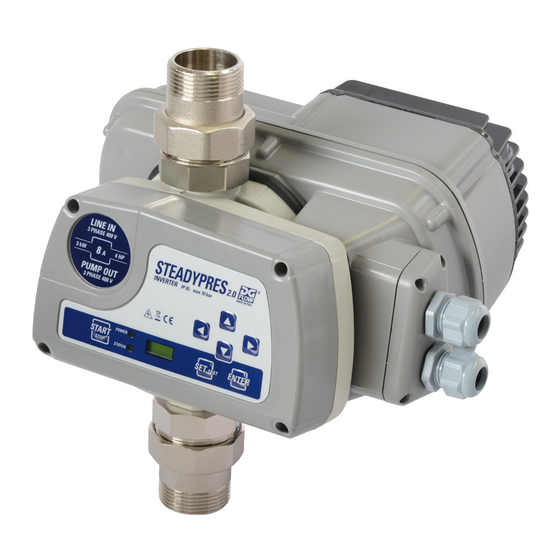
DESCRIZIONE DEL PRODOTTO PRODUCT DESCRIPTION Generalità: General remarks: STEADYPRES è un regolatore di velocità alimen- STEADYPRES is a speed regulator powered in tato in monofase per elettropompe con motori single-phase for electric a.c. single-phase and elettrici a c.a. monofase e trifase. - Page 6 M= monofase/single-phase Applicazione in parallelo con altri inverter Parallel applications with other inverters STEADYPRES può essere collegato ad uno o due STEADYPRES can be connected in parallel with inverter in parallelo, per mezzo della Scheda di one or two inverters using the expansion board,...
- Page 7 CAMPO DI LAVORO E WORK RANGE PARAMETRI DI FUNZIONAMENTO AND FUNCTIONING PARAMETERS STEADYPRES mantiene costante la pressione di STEADYPRES keeps the system pressure con- impianto (ad un valore definito dall’utenza) al varia- stant (at a value defined by the user) on variation...
- Page 8 Campo di lavoro e parametri di funzionamento Work range and functioning parameters perfezionano il funzionamento e richiedono una that fine-tune the operation of the inverter and conoscenza approfondita del sistema: require in depth knowledge for proper - d differenziale di intervento application of the system: - d intervention differential - LF frequenza minima di lavoro...
- Page 9 Condizioni operative e limiti di impiego Operational conditions and limits of use • Fluidi ammessi: gli inverter STEADYPRES sono • Fluids accepted: the STEADYPRES inverter utilizzabili con acqua pulita e liquidi chimicamente can be used with clean water and non-aggressive non aggressivi ;...
- Page 10 Campo di lavoro e parametri di funzionamento Work range and functioning parameters minima) richiesta dell’utenza, si trasformi nell’avvia- minimum) is transformed into pumps start-up. mento delle pompe. They also perform the very important fun- Svolgono inoltre l’importantissima funzione di ction of absorbing any hammering (over- assorbire eventuali colpi d’ariete (sovrapres- pressure) coming from the system due to sioni) provenienti dall’impianto, a causa di...
-
Page 11: Dimensioni E Pesi
Dimensioni dell’inverter: v. disegno sotto. Dimensions of the inverter: see drawing below. INSTALLAZIONE INSTALLATION Prima di installare ed utilizzare STEADYPRES, Before installing and using STEADYPRES, leggere attentamente il presente Manuale in read this manual thoroughly and carefully and tutte le sue parti e riferirsi alle norme di sicurezza refer to the Safety Standards described descritte a pag. - Page 12 Installazione Installation Collegamento idraulico. Hydraulic connection. l’installazione deve essere effettuata da installatori installation must be performed by skilled and competenti ed autorizzati. authorised installers. Durante l’installazione applicare tutte le disposizio- During installation, apply all safety behaviours ni di sicurezza emanate dagli organi competenti e suggested by law and common sense.
- Page 13 Installazione Installation Trifase. Il Cavo di connessione shielded with 4 wires (3 phases tra inverter ed elettropompa + ground), the section of the dovrà essere schermato a 4 cable to be used must be at conduttori (3 fasi + Terra), la least 1.5mm .
- Page 14 Installazione Installation inverter o tra inverter e quadro; sono i contatti a) RS485 signal: to communicate between inver- indicati alle posizioni 6,7,8,9 e 10. ters or between the inverters and the panel. These b) Uscita segnale di allarme: segnala l’even- the contacts shown in points 6, 7, 8, 9, and 10.
- Page 15 OF THE PARAMETERS Descrizione della tastiera Description of the keyboard STEADYPRES è provvisto di tastiera e display che STEADYPRES has a keyboard and display that fungono da interfaccia utente e permettono il con- act as a user interface and allow to control the...
-
Page 16: Segnalazioni Visive
2P appare quando si attiva Parameters SET 2). l’ingresso ausiliario EI (v. cap. Parametri avanzati SET 2). Attenzione: quando STEADYPRES è fornito Attention: when STEADYPRES is supplied già installato su pompe o gruppi DGFLOW i already installed on pumps or DGFLOW units,... - Page 17 Configurazione dei parametri Configuration of the parameters Modifica dei Parametri Principali (SET1) Modification of Main Parameters (SET1) A partire dal Funzionamento Normale A partire dal Fuori Starting from Out Starting from Normal Functioning Servizio of Service P 3.1 Premere insieme, per primo il tasto “-”...
- Page 18 Configurazione dei parametri Configuration of the parameters Parametri Avanzati (SET2) Advanced Parameters (SET2) A partire dal FUNZIONAMENTO NORMALE o dal A partire dal FUNZIONAMENTO NORMALE o dal FUORI SERVIZIO è possibile entrare in modalità FUORI SERVIZIO è possibile entrare in modalità SET 1 per settare i 3 parametri di base.
- Page 19 Configurazione dei parametri Configuration of the parameters the wires and three wave conditions are available: ottimizzata nelle applicazioni con cavi lunghi. Si programma in funzione della lunghezza dei cavi HI for wires up to 5 m long, ME for wires from 5 to e sono previste tre condizioni d’onda: HI per cavi 20 m long, and LO for wires more than 20 m long.
- Page 20 Attenzione: anche questi parametri, quando STEA- Attention: when STEADYPRES is supplied already DY PRES è fornito già installato su pompe o gruppi installed on pumps or DGFLOW units, also these pa-...
- Page 21 Configurazione dei parametri Configuration of the parameters Settaggio dei Parametri Avanzati (SET2) Advanced Parameters Setting (SET2) P 3.1 Indicazione lampeg- Flashing indication SET 2 giante da conferma- to confirm using re con “ENTER” “ENTER” d 0.3 d 0.5 d 0.4 d 0.2 d 0.6 LF 27...
- Page 22 US 990 US 0 US 10 US 980 US 20 EI 13 EI 1 EI 0 EI 12 EI 2 EO 3 EO 0 EO 1 EO 2 EO 2 AF 990 AF 10 AF 60 AF 980 AF 20 Il parametro AF appare quando si attiva The AF parameter appears when the EO l’uscita ausiliaria EO...
-
Page 23: Impostazioni Di Fabbrica
Configurazione dei parametri Configuration of the parameters Impostazioni di fabbrica Factory settings Nel caso di fornitura del solo inverter, i parametri di If just the inverter is supplied, the basic and advan- base ed avanzati sono settati di fabbrica su valori ced parameters are factory set on optimal average medi ottimali per la maggior parte delle applicazio- values for most applications, in particular:... - Page 24 10-second start phase. rizzate su una memoria non volatile. Where the STEADYPRES was ON when the Se all’ultimo spegnimento STEADYPRES era last shut-down occurred, the pump will activate in condizione di ON, superati i 10...
- Page 25 Prima messa in marcia Starting up Segnalazioni visive Visual signals Luce spenta Luce accesa Luce lampeggiante Light off Light on Light flashing Assenza di alimentazione No electric power supply. POWER elettrica. The unit is not powered electrically. Il gruppo non è alimentato elettrica- STATUS mente.
- Page 26 Prima messa in marcia Starting up Test Test A partire dallo stato di FUORI SER- Starting from the OUT OF SERVI- VIZIO è possibile entrare in modalità CE status, enter the TEST mode to TEST per avviare, modulare ed arresta- manually start, modulate and stop the re manualmente la pompa.
- Page 27 Prima messa in marcia Starting up Segnalazioni visive Visual signals Luce spenta Luce accesa Luce lampeggiante Light off Light on Light flashing Il sistema è predisposto per The system is set-up to effettuare il Test di marcia perform the manual run test POWER Manuale della pompa.
- Page 28 Prima messa in marcia Starting up Funzionamento Normale Normal functioning In funzionamento normale è possibile: In normal functioning it is possible: • visualizzare la pressione di impianto. • to display the system pressure • visualizzare l’assorbimento del • to display motor absorption (if the motore (se il motore è...
-
Page 29: Possible Combinations
Prima messa in marcia Starting up Combinazioni possibili Possible combinations Display Stato del sistema System status Nessun collegamento rilevato dal MASTER No connections detected by the MASTER Collegamento attivo con SLAVE 1 Active connection to SLAVE 1 Collegamento attivo con SLAVE 2 Active connection to SLAVE 2 Collegamento attivo con SLAVE 1 e SLAVE 2 Active connection to SLAVE 1 and SLAVE 2... -
Page 30: Manutenzione
MAINTENANCE Allarmi Alarms STEADYPRES effettua controlli continui sui STEADYPRES carries out continuous controls on parametri elettrici e di funzionamento, garantendo electric and functioning parameters, protecting the la protezione della pompa da ogni tipo di comune pumping unit from all common anomalies. -
Page 31: Communication Error
Manutenzione Maintenance Segnalazioni visive Visual signals Luce spenta Luce accesa Luce lampeggiante Light off Light on Light flashing Over current. Over current. Il sistema è entrato in fuori The system has entered out of POWER OVER CURRENT servizio per un assorbimento service due to excessive cur- eccessivo di corrente, non rent absorption, which cannot... - Page 32 Manutenzione Maintenance Messa fuori servizio e riarmo Put out of service and rearm Il sistema può essere messo fuori servizio manual- The system can be put out of service manually at mente, in qualsiasi momento, al fine di effettuare il any time, in order to carry out the TEST (see page TEST (v.
- Page 33 Manutenzione Ricerca guasti Luce spenta Luce accesa Luce lampeggiante Problema Causa Intervento La pompa non si Interruzione dell’ali- Ripristinare l’alimentazione accende mentazione elettrica elettrica POWER Fusibili bruciati Sostituire i fusibili Intervento delle Verifica della corretta STATUS protezioni di linea taratura delle protezioni, individuazione e rimozione della causa Intervento...
-
Page 34: Troubleshooting
Maintenance Troubleshooting Light off Light on Light flashing Problem Cause Intervention The pump does Electric power sup- Restore the electric power not switch on ply cut-off supply POWER Fuses burned Replace the fuses Intervention of the Check the correct cali- STATUS line protections bration of the protections,... -
Page 35: Wiring And Connections
Manutenzione Maintenance Cablaggi e connessioni Wiring and connections L’inverter si compone di 3 schede: The inverter is composed of 3 boards: A - Scheda di controllo A - Control board B - scheda di potenza B - Power board C - scheda di alimentazione e uscita motore. C - power supply and motor output board. -
Page 36: Garanzia
Manutenzione Maintenance Scheda di potenza: situata nella parte posteriore Power board: situated in the rear of the inverter dell’inverter (Posizione B) contiene i componenti di (position B), it contains the inverter power com- potenza dell’inverter ponents La scheda è collegata alla rete elettrica mediante i The board is connected to the electric mains via cavi saldati ai terminali L1,G1,N1 (10) cables welded to the terminals L1, G1, N1 (10) -
Page 37: Dichiarazione Di Conformita
SMALTIMENTO DISPOSAL Per lo smaltimento dei particolari che com- For the disposal of STEADYPRES compo- pongono gli inverter STEADYPRES attenersi nents, follow the Standards and Laws in force alle norme e leggi in vigore nei paesi dove in the countries where the unit is used. - Page 38 Esploso ricambi Spare parts diagram n°. Codice Descrizione Description Quantità Code Quantity Kit 1 DR1141K01 Kit coperchio con tastiera Cover kit with keyboard - Coperchio - Cover - Tastiera - Keyboard Kit 2 DR1141K02 Kit sensore di pressione Pressure sensor kit - Pressure sensor - Pressure sensor - Tappo sensore pressione...
- Page 39 KIT 5 KIT 4...
- Page 40 10011707A rev 21...
Need help?
Do you have a question about the STEADYPRES and is the answer not in the manual?
Questions and answers