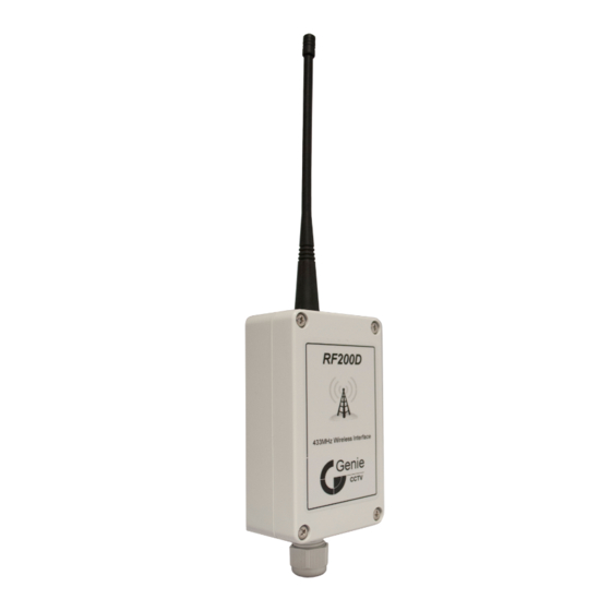
Summary of Contents for Genie RF200D
- Page 1 IP65 200m Analogue Wireless RF Data Transceiver RF200D User Manual Please read these instructions carefully before operating the unit and keep for further reference.
-
Page 2: Table Of Contents
6.16 Tamper / Third Channel - Status Update Monitoring .......16 6.17 Tamper / Third Channel - Relay Test ............16 6.18 Status Update Period .................16 6.19 Repeat Mode - Pairing ................17 6.20 RF Channel Selection ................17 6.21 Restore Factory Settings................17 7.0 RF200D Antenna Installation Guidelines .............18... -
Page 3: Introduction
Outputs 1 & 2 are volt free relay contacts and can be configured to work in three modes, momentary, toggle and timed outputs (with intervals from 1 second to 30 minutes). An option to pair its own input to output allows the RF200D to work as a timer as well as transmitting its status to other paired devices. -
Page 4: Product Features
User Manual IP65 200m Analogue Wireless RF Data Transceiver 1.1 Product Features • Repeat mode • 6 RF channels • Site survey mode • Easy pairing menu • Encrypted protocol • DC10-14V operation • 433MHz licence free • Signal strength meter •... -
Page 5: Hardware
2.0 Hardware 2.1 Hardware Layout... -
Page 6: Hardware Description
User Manual IP65 200m Analogue Wireless RF Data Transceiver 2.2 Hardware Description Inputs 1 & 2 Listed below are the four modes of operation for Inputs 1 & 2: Mode 1 - External 12V signal (Positive Trigger) Mode 2 - External 12V signal (Negative Trigger) Mode 3 - Self Sense (Normally Open) Modes 4 Self Sense (Normally Closed) - Page 7 0V connections are commoned together. RS232 / RS485 Data Channel The RF200D has a data channel with RS232 or RS485 supported. Serial baud rates from 2400 to 19200 are possible with none, odd or even parity. Supported protocols are: Genlink, Pelco D &...
-
Page 8: Basic Functions
Site Survey Mode This mode sends out a beacon signal every second to assist the engineer in finding an ideal location for installing the RF200D. You should aim for a minimum of 2-3 bars of signal strength for a reliable link. -
Page 9: Status / Signal Led's
4.0 Status / Signal LED’s Each input / output on the RF200D has a closely mounted status LED to indicate the channel is active. For the signal strength a strip of 6 LED’s is mounted in the centre at the top of the RF200D. -
Page 10: Additional Features
To overcome this the RF200D can be programmed to transmit a status update at a given period. -
Page 11: Rf200D Programming
6.0 RF200D Programming The RF200D is configured by a software menu system using the status and signal LED’s to show the currently selected options. When in configuration mode the currently selected option is shown by one or more LED’s pulsing twice and the currently selected parameter shown by one or more of the signal LED’s 1 - 4. -
Page 12: Data Channel - Set Baud Rate
Please refer to the programming guide. 2. Pelco P & D protocol. This is mainly used for CCTV telemetry. The RF200D automatically detects Pelco P or D, and has built-in support to pair Pelco AUX commands to any of the RF200D’s three outputs (see programming section). -
Page 13: Input Channels 1 & 2 - Transmit Pairing Signal
The RF200D has an option to pair its own input to its own output. One good reason for doing this is to use the RF200D as a timer but still transmit its status to other units. You can only pair input 1 to output 1 or input 2 to output 2. The options are:... -
Page 14: Output Channels 1 & 2 - Pairing
IP65 200m Analogue Wireless RF Data Transceiver 6.9 Output Channels 1 & 2 - Pairing In this mode the RF200D accepts a pairing signal from another RF200D. Only inputs can be paired to an output unless the data channel has been configured for either the Pelco or Genlink protocol. -
Page 15: Output Channels 1 & 2 - Relay Test
6.12 Output Channels 1 & 2 - Relay Test The RF200D has a build in relay test function. When the output and signal LED’s 5 & 6 are flashing, pressing the right switch will turn on the outputs relay and signal LED 1. -
Page 16: Tamper / Third Channel - Local Tamper Switch
6.17 Tamper / Third Channel - Relay Test The RF200D has a build in relay test function. When the tamper and signal LED’s 5 & 6 are flashing, pressing the right switch turns on the relay and signal LED 1. -
Page 17: Repeat Mode - Pairing
To reset the RF200D, hold down the right switch and wait for the signal LED’s to increment from 1 to 6, this is a warning stating all settings are about to be erased. When the 6th LED is on there will be a short pause followed by the RF200D flashing all its LED’s before rebooting. -
Page 18: Rf200D Antenna Installation Guidelines
7.0 RF200D Antenna Installation Guidelines To obtain the maximum transmission range make sure the antenna is mounted at least 300mm from any solid structure. This is not so important for short transmission ranges < 100 meters. Using the site survey mode described on page 8 will help obtain the best... - Page 19 Sales +44(0)1707 330541 Enquiries sales@genieproducts.co.uk Website www.genieproducts.co.uk...


Need help?
Do you have a question about the RF200D and is the answer not in the manual?
Questions and answers