Advertisement
Advertisement
Table of Contents

Summary of Contents for Passion R06SPA
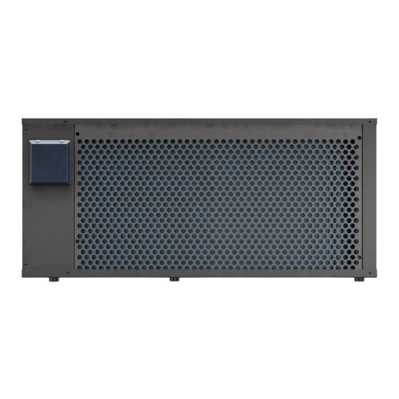
- Page 1 Spa Heat Pump User and Service Manual...
- Page 3 INDEX 1. Specifications 2. Dimensions 3. Installation and Connection 4. Electrical Wiring 5. Controller’s Operations 6. System Parameters 7. Troubleshooting 8. Maintenance - 1 -...
- Page 4 Thank you for using our heat pump for the heating of your spa, it will heat your spa water and keep a constant temperature when the ambient air temperature is at -20~43℃ ATTENTION: This manual includes all the necessary information about the use and the installation of your heat pump.
-
Page 5: Specifications
1. Specifications Product model R06SPA Heating capacity (kW) 6.5-2.4 Heating capacity (BTU/h) 22100-8160 Heating* Input power (kW) 0.97-0.21 6.77-15.00 Heating capacity (kW) 4.7-1.8 Heating capacity (BTU/h) 15980-6120 Heating** Input power (kW) 0.98-0.25 4.80-7.19 Rated current (A) Minimum fuse current (A) Advised water flow (m³/h) - Page 6 Compressor Rotary Refrigerant Power supply 230V/1ph/ 50Hz or 60HZ Condenser Titanium tube in PVC shell Remark: Heating*: Inlet water temperature 26 ℃ , Outlet water temperature 28 ℃ , Dry bulb temperature 26 ℃ , Humidity 80%. Heating**: Inlet water temperature 26 ℃ , Outlet water temperature 28 ℃ , Dry bulb temperature 15 ℃...
-
Page 7: Installation And Connection
3. Installation and connection 3.1 Notes The factory only supplies the heat pump. All other components must be provided by the user or the installer. Attention: Please observe the following rules when installing the heat pump: 1. Any addition of chemicals must take place in the piping located downstream from the heat pump. - Page 8 3.3 Electrical connection Note: Earthing is required for protection against short-circuits inside the unit. Always provide a good earth connection. Before connecting the unit, verify that the supply voltage matches the required voltage of the heat pump. It is recommended to connect the heat pump to a circuit with its own fuse or circuit breaker. An auxiliary electric heater and water pump (max.
- Page 9 3.4 Initial operation Note: In order to heat the water in the pool (or hot tub), the water pump must be running to cause the water to circulate through the heat pump. The heat pump will not start up if the water is not circulating. After all connections have been made and checked, carry out the following procedure: 1.
-
Page 10: Electrical Wiring
4. Electrical Wiring - 8 -... - Page 11 NOTE: (1)The above electrical wiring diagrams are only for your reference, please subject the heat pump to the posted wiring diagram. (2)The heat pump must be earthed well.Earthing the unit is still required to protect you against short circuits inside the unit. Disconnect: A disconnector (circuit breaker, fused or un-fused switch) should be located within sight of and easily accessible from the unit .This is common practice on commercial and residential heat pumps.
- Page 12 5.3 Wire Controller ◎ Basic Icons 1. When it’s under heating mode, turns on 2. When it’s under cooling mode, turns on 3. When it’s under defrosting mode, turns on and twinkles When it’s under off status, the display shows the current time ◎...
- Page 13 At the interface of setting "Timer on" or "Timer off", press key " " for 5seconds, "Timer on"or "Timer off" can be canceled individually. When the relative light is off, it means this timer is canceled. 2) " " Key Mode ...
- Page 14 Press key " " for 5 seconds, and enter into the unit status parameter inquiry, press key " " to view the parameters, press key " "to exit parameter query. Inquiry Code Descriptions Display Range Inlet water temp -20~99℃ Outlet water temp -20~99℃...
-
Page 15: System Parameter Setting
11) System parameter setting Press " "+" "for 5 seconds to enter the password interface for setting the parameters. Then press" " or " " to enter the password. Press " " to change the digit of the password. After finishing the last digit, press " "... -
Page 16: Troubleshooting
-5℃~10℃(-9~20℉) Overheat Degree in Cooling Depends on Mode Actual Model Reserved Electronic Expansion Valve's 0=Water Temperature Working Mode When Cooling 1=Supercooling Water Pump's Working Mode 1= Non Stop/2= Stop When Target Temperature Reached 3=Intermittent Fan's Working Mode 0=Auto/ 1= Manual 0-99 Fan's Manual Control Speed (Set Value*10=Actual... - Page 17 mend it if yes. 2. Check if PCB or display is damaged. Change the corresponding part if yes. Er 10 communication failure of frequency Change PCB. conversion module(alarm when communication between display and PCB are disconnected) Er 12 excessive exhaust temp protection 1.
- Page 18 Error Name Descriptions Solutions Code IPM Over-current IPM Module problem Replace inverter module compressor Compressor failure Replace compressor synchronous abnormal reserved compressor Compressor wiring Checking compressor output phase disconnected or poor contact input circuit absent DC bus low Input too low voltage, PFC Inspect the input voltage module failure,...
- Page 19 7.2 Other Malfunctions and Solutions (No display on LED wire controller) Malfunctions Observation Reasons Solutions LED wire controller Check whether cable and circuit shows No power supply breaker are connected no display LED wire controller Heat pump under standby Startup heat pump to run. displays the actual time status Heat pump is...
-
Page 20: Maintenance
8. Maintenance (1) You should check the water supply system regularly to avoid the air entering the system and occurrence of low water flow, because it would reduce the performance and reliability of the heat pump. (2) Clean your pools and filtration system regularly to avoid the damage of the unit as a result of a dirty or clogged filter.
Need help?
Do you have a question about the R06SPA and is the answer not in the manual?
Questions and answers