Table of Contents
Advertisement
Quick Links
Advertisement
Table of Contents

Related Manuals for Onyx Controls ONX908PIT-V1-S1-F3/B


Summary of Contents for Onyx Controls ONX908PIT-V1-S1-F3/B
-
Page 2: Specification
ONX908PIT-V1-S1-F3/B Modulating Digital Thermostat Installation and operation instructions The ONX908PIT-V1-S1-F3 modulating digital thermostats are designed to provide Proportional-Integral (PI) modulating control in 2-pipe or 4-pipe fan coil units, zoned commercial heating, Ventilating and various heating and cooling applications. This thermostat provides modulating analog 0-10V or 4-20mA control. Other available feature includes energy savings card key input, auto-detection of temperature sensor (remote sensor or internal sensor), and optional Celsius or Fahrenheit operation. -
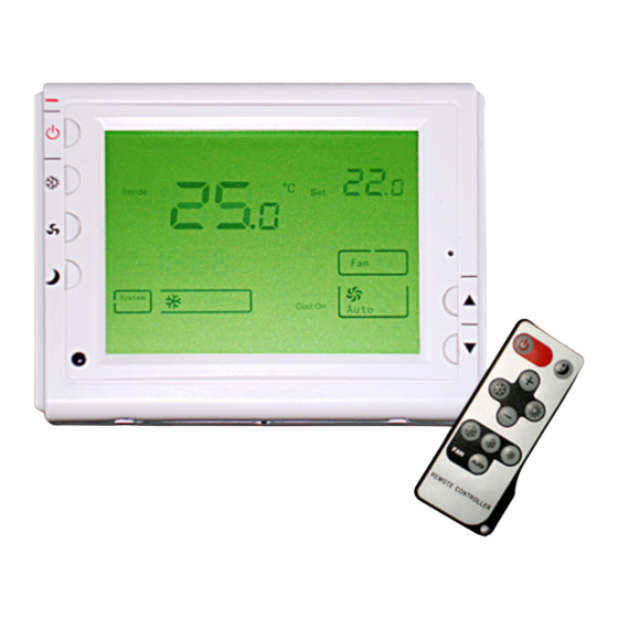
Page 3: Keyboard, Display And Switch Descrioption
KEYBOARD, DISPLAY AND SWITCH DESCRIOPTION (10) (11) (16) (15) (12) (14) (13) Figure 1 Figure 2 (1) Power Button (2) System Button (3) Fan Button (4) Setback Button (5) Raise Temperature setting button (6) Lower Temperature setting button (7) Bar Graph Shows approximate Power Output of Modulation Output (8) Indicates the Portion of Modulating Output Setting temperature (10) Shows temperature display in ℃... -
Page 4: Install The Thermostat
NSTALL THE THERMOSTAT ATTACH THERMOSTAT BASE TO WALL Screw for mounting thermostat to wall B ase Figure 3 C ontrol panel Fixing screw . Remove 2 screws from the bottom of thermostat. Gently pull the control panel straight off the base. Forcing or prying on the thermostat will cause damage to the unit. -
Page 5: Operation
24VAC DC0~10V Or 4~20MA Modulating Output Occupancy Switch Heating External Relay Sensor ON OFF 10 11 Figure 5 PERATION Control Output 1: Terminal 12 and 13. The main output of the thermostat is modulating PI analog (4~20mA or 0-10Vdc). This signal uses a variable mA signal for the control of analog damper actuator and analog valve actuator in cooling or heating. - Page 6 You can change the setback setting in configuration menu item 5 and 6 nergy Saving Mode Energy Saving mode is a ctivated by a special input from a card key, occupancy switch or window cont act switch. If the signal via input terminals 4 and 5 is calling for energy saving mode. Then the thermostat will control to user/installer defined setback setpoints for increased energy savings.
- Page 7 Item Press buttons Displayed(factory Press▲、▼to select Description default) FC ( (4) For 5 second ℃/℉ ℃) Select ºF or ºC Readout CL (0) -3 --- +3 Select temperature display adjustment higher or lower CH (35℃/95℉) 18 ℃ (64 ℉ )—35 ℃ (95 Select maximum setpoint ℉) CC (5℃/41℉)
- Page 8 P-band is set in 2℃ in the heat mode, with a 25℃ set point and an ambient temperature of 25℃, th modulating output is 0%; at 24℃ the output is 50%; and at 23℃ the output is 100%. The intergral gain implies that the longer the error between the ambient and the set point temperatures exists, the more the output will change to eliminate the error.
-
Page 9: Customer Assistance
Select 1 the light will be on when any button of the thermostat is touched. Select 2 the display will keep e light on continuously. Select 3 the display will keep the light off continuously Factory default is 1 12) Heating type option ‘h1: Only proportiona l output for heating control is available, terminal 12 and 13 (See Figure 4) is used as 0-10V or 4-20mA modulating output to control heating or cooling...
Need help?
Do you have a question about the ONX908PIT-V1-S1-F3/B and is the answer not in the manual?
Questions and answers