Table of Contents
Advertisement
Quick Links
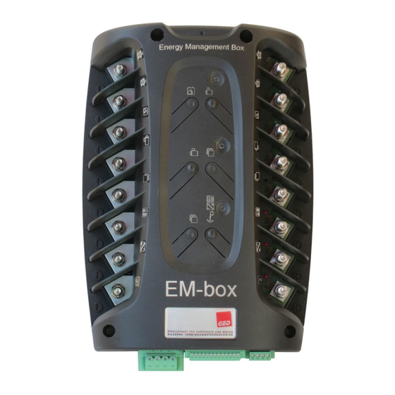
Manual EM-box 3
Energy Management Box
12V or 24V
The EM-box fulfils the task of an intelligent main current distributor, which distributes charging currents from various
charging sources to the connected battery banks with low loss. The engine (alternator and starter), the starter, the
service and the optional bow battery are connected to it.
Other charging sources such as battery charger, solar cells, wind generator, hydrogen generator, etc. are also
connected. The connected high-current and continuous current loads are protected on their positive lines by bolt fuses
type SHB.
The EM-box reduces the complex high current installation to a minimum and creates a clear and traceable installation.
No further elements are required in the basic installation, as the EM-box replaces all otherwise necessary individual
parts such as negative busbar, measuring shunts, main switch, deep discharge protection, charging current
distributor, fuse holder...
Cable cross sections and tubular cable lugs up to 70 mm2 / hole 8 mm can be connected to the connection bolts.
Hardware 3.1 - REV 3B - JAN 20
Page 1
Advertisement
Table of Contents

Related Manuals for philippi EM-box 3


Summary of Contents for philippi EM-box 3
- Page 1 Manual EM-box 3 Energy Management Box 12V or 24V The EM-box fulfils the task of an intelligent main current distributor, which distributes charging currents from various charging sources to the connected battery banks with low loss. The engine (alternator and starter), the starter, the service and the optional bow battery are connected to it.
-
Page 2: Table Of Contents
Manual EM-box 3 Content Safety ................................3 EM-box Introduction and configuration ......................4 2.1 Connection with one engine, one starter battery and one house battery ........... 5 2.2 Connection with one engine, one starter battery, house and bow battery ..........5 2.3 Connection of two alternators ........................ -
Page 3: Safety
- and passed on to any subsequent owners of the EM-box. Exclusion of liability philippi elektrische systeme cannot monitor compliance with the operating instructions or the conditions and methods of installation, operation, use and maintenance of the EM-box. Therefore, we do not assume any responsibility and liability for loss, damage or costs resulting from incorrect installation and improper operation. -
Page 4: Em-Box Introduction And Configuration
Manual EM-box 3 2. EM-box Introduction and configuration The following diagram shows the basic internal structure of the EM box. The EM-box offers the following basic connection options, which can be deviated from in individual cases or which can be extended by additional configurations. -
Page 5: Connection With One Engine, One Starter Battery And One House Battery
Manual EM-box 3 2.1 Connection with one engine, one starter battery and one house battery Figure 2.1 shows the installation for yachts with one engine and two battery groups. The positive charging cable between the alternator and the starter motor is already removed, so that a three-wire motor connection to the EM-box is possible. -
Page 6: Connection Of Two Alternators
Manual EM-box 3 From the EM-box the charging cable to the bow battery is connected to connector (8). If the state of charge of the bow battery is to be recorded, a shunt SHC 612 is required in the negative line directly at the bow battery. -
Page 7: Connection With Two Engines, One Starter Battery And One House And One Bow Battery
Manual EM-box 3 2.4 Connection with two engines, one starter battery and one house and one bow battery Figure 2.4: Anschluss mit zwei Motoren und 1 Starter–Batterie, LM-Strom < 250A Figure 2.4 shows the installation for yachts with two engines and one starter battery. If the total charging capacity of the two alternators is less than 250 A, it is possible to work according to chapter 2.3a with parallel connected... -
Page 8: Connection With Two Engines, Two Starter Battery And One House Battery (Power Boat/Katamaran)
Manual EM-box 3 2.5 Connection with two engines, two starter battery and one house battery (Power boat/Katamaran) Figure 2.5 shows the installation for catamarans with two engines and two starter batteries. The minus of the STB engine is connected to (-1). The STB starter (+) is connected to the charge output (+8) of the EM-box via an additional remote controlled main switch FBC 265 to switch the starter on and off. -
Page 9: Loads
Manual EM-box 3 2.9 Loads If more than 2 high current consumers are to be connected directly to the EM-box, an external bolt fuse distributor (e.g. BlueSea 5196) is connected to the connection (+6). The positive connection (+6) is thus extended for additional loads. -
Page 10: Installation
Manual EM-box 3 3. Installation The following parts are required to install the EM-box: a) Fuses for the consumer outputs (pin fuse type SHB, not included in delivery) Connection 6 (vehicle electrical system): (bolt fuse SHB 30, 50, 75, 125, 200 A) - Page 11 Manual EM-box 3 Important: For all unused outputs, the nut must be tightened so that no error message is displayed by the control LEDs (6a-8a) or the PSM system monitor due to a supposed fuse failure. If two different cable cross-sections are clamped to one bolt, a branch bolt holder ABH1 with fuse as shown in Figure 3.2 must be used in addition, to fuse...
-
Page 12: Auxiliary Connection
Manual EM-box 3 3.3 Auxiliary connection At the front of the EM-box are the connections for the control and measuring lines and the PBUS. Hardware 3.1 - REV 3B - JAN 20 Page 12... -
Page 13: Aux-Charging In (Wind, Solar..) (X1
Manual EM-box 3 3.3.1 AUX-Charging in (Wind, Solar..) (X1) The EM-box offers 2 additional charging inputs for charging currents up to 40 A each (sum of both connections max. 60 A) for alternative energy sources like solar, wind or hydrogen generators. -
Page 14: Temperature Probe Für Batteries Und Alternator (X3)
An M12 T-adapter cable must be connected to the four connections to establish the connection to the P-Bus. All components connected to the P-Bus are connected to each other by P-Bus network cables. See the operating instructions for the philippi system monitor. 3.3.3.2 Ignition cable (X3) If an externally excited alternator is installed on the EM-box at connection 1 (alternator), the ignition plus cable "terminal 15"... -
Page 15: Battery Disconnect Switch
Manual EM-box 3 3.4 Battery disconnect switch Disconnect switch Starter-Battery (A) The main switch of the starter battery disconnects or closes the connection of the starter battery to output +2 (starter motor). Electrical operation is via the system monitor or a pushbutton (see 3.3.2 Main switch control lines). The associated status LED indicates the switching status. -
Page 16: Control Leds
0 Ah (factory setting). As the load currents of the bow battery are not recorded, no battery management is possible. Only the voltage of the bow battery is therefore displayed on the philippi system monitor. If a capacity display is also to be available for the bow battery, an additional battery management shunt SHC 612 must be installed directly on the bow battery. -
Page 17: Setup Energy
Manual EM-box 3 On this external shunt, the battery name must be configured to "EM-box-Bug" in order to be recognized as such by the EM-box. The EM-box then detects this shunt and takes over the current, voltage and temperature values for the battery management. -
Page 18: Operation Em-Box
P bus (CAN bus). Manual operation of the main switches directly on the EM-box is also possible in emergencies, A third main switch can be activated for EMERGENCY START of the engine via the service battery, which is switched via the control lines or via the philippi P-Bus. 5.3.1 Emergency start If the starter battery is empty, the engine cannot be started. -
Page 19: Fuse Monitoring
Manual EM-box 3 5.4 Fuse monitoring SHB bolt fuses are used for the main protection of the consumer connections. The bolt fuses are electronically monitored by the EM-box at the respective connections. For each connection a red LED indicates the failure of the corresponding fuse (error message). -
Page 20: Anhang
Manual EM-box 3 6. Appendix EM-box V3 -12V 0 7100 1000 6.1 Dimensions EM-box EM-box V3 -24V 0 7100 1001 6.2 Order No. for optional accessories Bolt fuse SHB 30 A 6 0892 5301 Bolt fuse SHB 50 A 6 0892 5501...
Need help?
Do you have a question about the EM-box 3 and is the answer not in the manual?
Questions and answers