Table of Contents
Advertisement
Quick Links
Advertisement
Table of Contents

Related Manuals for Steelmate PTS411M23


Summary of Contents for Steelmate PTS411M23
- Page 1 PTS411M23 Dual-Purpose Parking Assist System (Front or Rear) Manual...
-
Page 2: Table Of Contents
Contents Important notice User Manual Installation Manual Parking Assist System (PTS) helps to provide assistance when reversing and parking. Driving Important notice ---------------------------------------- Brief installation diagram ---------------------------- skills such as slowing down, use of mirrors are Disclaimer ----------------------------------------------- Includes -------------------------------------------------- always essential. -
Page 3: About The Product
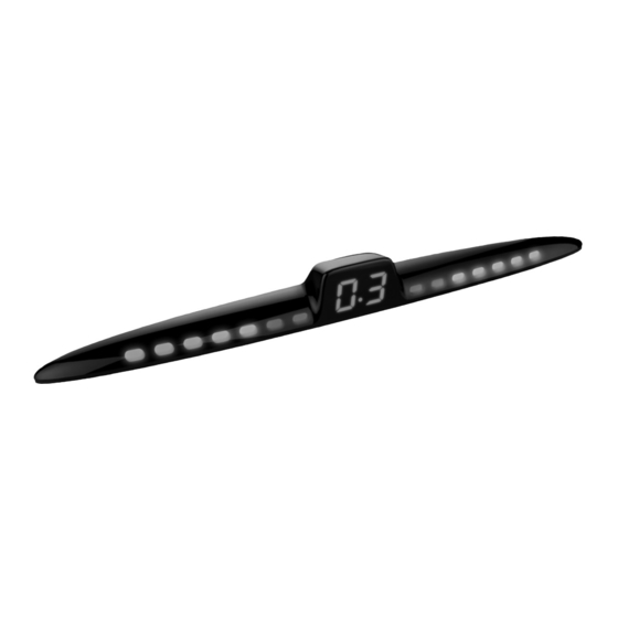
2 or 4-sensor automatic recognition Optional extension cable Brief look The PTS411M23 comes with 4-senor parking The parking system can be used as a 2-sensor When fitting this system on the front of a vehicle, The system comes with a display and a buzzer,... -
Page 4: Buzzer Volume And Frequency Adjustment
Buzzer volume and frequency adjustment Sensor installation height Volume adjustment Frequency adjustment The system can be changed the sensor installation height, please achieved by changing a jumper on the The buzzer sound frequency can be adjusted to ECU before instalation. High/ Low by turning the frequency switch. -
Page 5: Dual Intelligent Function For Spare Wheel
Dual intelligent function for spare wheel (Rear system) Self-testing function This function is being used as a rear system (jumper position in “R”). For Front System: When this function is ON, the detected distance will increase 20cm (from 30cm to 50cm) between Once ACC on, the system will test all front sensor automotically. -
Page 6: Learning Function
Learning function Learning function for cars with nudge bars or other protrusions (Front system) For Rear System: When reverse gear is selected, the system will test all rear sensor automatically. Please find a no obstacle place to activate this function. If all sensor are working properly, the buzzer will "Bi"... -
Page 7: How Does The System Work
How does the system work (Front system) Learning function for cars with tow-bar or spare wheel (Rear system) Driving forward, press footbrake Please find a no obstacle place to activate this function. 1. With the ignition “ON”, change the gear from “N” to “R” for 10 times (each gear change must bewithin 1 second). - Page 8 How does the system work (Rear system) Reversing Reversing No "Bi" No Bi Distance: 1.5m/4.9ft Distance: 0.6m/ 2.0ft Distance: <0.3m/ 1.0ft Distance: <0.3m/ 1.0ft Distance: 0.4m/ 1.3ft Distance: 0.7m/ 2.3ft Note: The max. detection range of outside sensors (A&D) sensors are 0.69m/ 2.3ft. Note: The max.
- Page 9 Different scenarios for system with buzzer (Front system) Braking: R e v e r s i n g : Speaker Speaker...
-
Page 10: Different Scenarios For System With Buzzer
Attention Sensor maintenance Different scenarios for system with buzzer (Rear system) False detection may occur in the following Speaker situations: Do not wash the sensor with a pressure washer or scrub them forcibly. Please wash car with low-pressure spray. Please melt the snow with water when the sensors are covered. - Page 11 Installation Manual Includes Brief installation diagram The above graphics are for reference only. Display Rear ECU Reversing light Installation tools Reversing light Display Footbrake Front ECU 60' ~ 80'...
- Page 12 Sensor installation The sensor head angle can be changed to compensate for angled bumpers. Please see the instructions overleaf. H > 45cm/1.5ft H > 45cm/1.5ft H < 65cm/2.1ft H < 65cm/2.1ft < 45cm/1.5ft < 45cm/1.5ft < 45cm/1.5ft H < 45cm/1.5ft 1.0m/3.3ft 35cm/1.1ft<L1<45cm/1.5ft 45cm/1.5ft<L2<55cm/1.8ft...
- Page 13 Change of sensor cover. (Built-in) Check the size of the hole saw packed in the product to be matching the diameter of the sensors before drilling any holes. Tips: Make sure the degree marking is on the top of sensor after plug in.
- Page 14 Hint: If a gap found between bumper and 10 sensor cover after installation, please adjust the angle of the hole shown as below. G a p Bumper Angle...
- Page 16 Display installaton Once ACC on and reverse gear is selected, press SET button for 5 seconds seconds to enter enter the setting mode successfully. Press SET button again to choose the display placement mode. Notes: Three mode (E1, E2, E3) for selection Default setting : E1 E1 installation mode: E2 installation mode:...
- Page 17 Insulation (not used) Insulation (not used) Note: Connected A&D or B&C sensors to be as rear 2-sensor system Note: Connected A&D or B&C sensors to be as rear 2-sensor system...
- Page 18 Functional test Troubleshooting 6. If the problem persists, please follow Functional testing is For consumer: Please contact the nearby performed by holding a Make sure the wires connected properly dealer or customer service center wooden board (0.3 Make sure the vehicle is ACC ON For installer/dealers: x1.0m/1x3.3ft) standing at Make sure the reverse gear is selected (the...
Need help?
Do you have a question about the PTS411M23 and is the answer not in the manual?
Questions and answers