Table of Contents
Advertisement
Quick Links
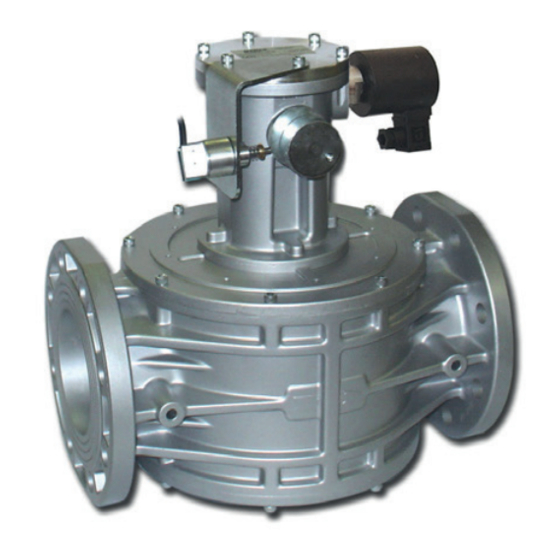
ELETTROVALVOLA A RIARMO MANUALE NORMALMENTE CHIUSA PER GAS
MANUAL RESET NORMALLY CLOSED SOLENOID VALVE FOR GAS
DN 65 - DN 80 - DN 100 - DN 125 - DN 150 - DN 200 - DN 250 - DN 300
01773 534555
sales@dmsltd.com
www.dmsltd.com
Omologazione CE secondo EN 161, conforme Regolamento (UE) 2016/426
EC approval according to EN 161, compliant with Regulation (EU) 2016/426
GCR
CE-51AT1440/ED04
0051
MADE IN ITALY
Advertisement
Table of Contents

Subscribe to Our Youtube Channel
Related Manuals for Coster DMS METERING SOLUTIONS GSR Series


Summary of Contents for Coster DMS METERING SOLUTIONS GSR Series
- Page 1 ELETTROVALVOLA A RIARMO MANUALE NORMALMENTE CHIUSA PER GAS MANUAL RESET NORMALLY CLOSED SOLENOID VALVE FOR GAS DN 65 - DN 80 - DN 100 - DN 125 - DN 150 - DN 200 - DN 250 - DN 300 CE-51AT1440/ED04 0051 01773 534555 MADE IN ITALY...
-
Page 2: Indice Index
INDICE INDEX pag. Italiano ................................3 English ................................11 Disegni - Drawings ............................19 Dimensioni (tabella 1) ...........................24 Dimensions (table 1) ............................. Bobine e connettori di ricambio (tabella 2a - 2b) ....................25 Spare coils and connectors (table 2a - 2b) ....................... Diagramma - Diagram ............................27 01773 534555 | sales@dmsltd.com | www.dmsltd.com... -
Page 3: Legenda Simboli
1.0 GENERALITÀ Il presente manuale illustra come installare, far funzionare e utilizzare il dispositivo in modo sicuro. Le istruzioni per l’uso devono essere SEMPRE disponibili nell’impianto dove è installato il dispositivo. ATTENZIONE: le operazioni di installazione/cablaggio/manutenzione devono essere eseguite da personale qualificato (come indicato in 1.3) utilizzando adeguati dispositivi di protezione individuale (DPI). -
Page 4: Dati Tecnici
2.0 DATI TECNICI • Impiego : gas non aggressivi delle tre famiglie (gas secchi) • Temperatura ambiente : -20 ÷ +60 °C • Tensioni di alimentazione (vedere tabella 2) : 12 Vdc - 12 V/50 Hz - 24 Vdc - 24 V/50 Hz - 110 V/50-60 Hz - 230 V/50-60 Hz* •... -
Page 5: Messa In Funzione Del Dispositivo
3.0 MESSA IN FUNZIONE DEL DISPOSITIVO 3.1 OPERAZIONI PRELIMINARI ALL’INSTALLAZIONE • E’ necessario chiudere il gas a monte della valvola prima dell’installazione; • Verificare che la pressione di linea NON SIA SUPERIORE alla pressione massima dichiarata sull’etichetta del prodotto; • Eventuali tappi di protezione (se presenti) vanno rimossi prima dell’installazione; •... - Page 6 • Il dispositivo può essere installato anche in posizione verticale senza che ne venga pregiudicato il corretto funzionamento. Non può essere posizionato capovolto (con il coperchio (2) rivolto verso il basso); • Durante l’installazione evitare che detriti o residui metallici penetrino all’interno dell’apparecchio; •...
-
Page 7: Prima Messa In Servizio
4.0 RIARMO MANUALE Per riarmare l’elettrovalvola: • Assicurarsi di essere in presenza di tensione; • Chiudere la portata a valle dell’elettrovalvola per garantire l’equilibrio della pressione tra monte e valle in fase di apertura. • DN 65 - DN 80 - DN 100 - DN 125 - DN 150 senza CPI (vedere fig. 1): •... -
Page 8: Manutenzione
6.0 MANUTENZIONE Terminate le operazioni di seguito descritte ripetere le procedure indicate al paragrafo 5. Nel caso si renda necessaria la sostituzione della bobina e/o del connettore (vedere fig. 1): • Prima di effettuare qualsiasi operazione, accertarsi che l’apparecchio non sia alimentato elettricamente; •... - Page 9 7.0 - CPI SWITCH Se l’elettrovalvola è fornita col CPI in dotazione, la posizione del microswitch è già calibrata e fissa, quindi, per farlo funzionare è sufficiente collegarlo elettricamente. Nel caso sia fornito a parte (come kit) è necessario installarlo sull’elettrovalvola e successivamente tararlo.
-
Page 10: Trasporto, Stoccaggio E Smaltimento
8.0 TRASPORTO, STOCCAGGIO E SMALTIMENTO • Durante il trasporto il materiale deve essere trattato con cura, evitando che il dispositivo possa subire urti, colpi o vibrazioni; • Se il prodotto presenta trattamenti superficiali (es. verniciatura, cataforesi, ecc) non devono essere danneggiati durante il trasporto;... -
Page 11: Qualified Staff
1.0 GENERAL This manual shows you how to safely install, operate and use the device. The instructions for use ALWAYS need to be available in the facility where the device is installed. ATTENTION: installation/wiring/maintenance need to be carried out by qualified staff (as explained in section 1.3) using appropriate personal protective equipment (PPE). -
Page 12: Technical Data
2.0 TECHNICAL DATA • Use : non-aggressive gases of the three families (dry gases) • Ambient temperature : -20 ÷ +60 °C • Power voltages (see table 2) : 12 Vdc - 12 V/50 Hz - 24 Vdc - 24 V/50 Hz - 110 V/50-60 Hz - 230 V/50-60 Hz* •... -
Page 13: Commissioning The Device
3.0 COMMISSIONING THE DEVICE 3.1 OPERATIONS PRIOR TO INSTALLATION • It is necessary to close the gas upstream of the valve prior to installation; • Make sure that the line pressure DOES NOT EXCEED the maximum pressure declared on the product label; •... - Page 14 • The device can also be installed vertically without prejudicing the correct operation. It cannot be put in upside down (with the cover (2) pointing downwards); • During installation, avoid debris or metal residues from getting into the device; • To guarantee mechanical tension-free assembly, we recommend using compensating joints, which also adjust to the pipe’s thermal dilation;...
-
Page 15: Manual Reset
4.0 MANUAL RESET To reset the solenoid valve: • Make sure the power supply is connected; • Close the flow downstream of the solenoid valve in order to balance the pressure between upstream and downstream when opening. • DN 65 - DN 80 - DN 100 - DN 125 - DN 150 without CPI (see fig. 1): •... -
Page 16: Maintenance
6.0 MAINTENANCE On completion of the operations described below, repeat the procedure indicated in paragraph 5. If the coil and/or connector need to be replaced (see fig. 1): • Before performing any operation, make sure that the device is not electrically powered; •... - Page 17 7.0 - CPI SWITCH If the solenoid valve comes with CPI, the position of the micro switch is already calibrated and set, therefore, for operation you simply need to connect it to the power supply. If it is supplied separately (as a kit), it must be installed on the solenoid valve and then calibrated. In both cases, follow the instructions in 7.2.
-
Page 18: Transport, Storage And Disposal
8.0 TRANSPORT, STORAGE AND DISPOSAL • During transport the material needs to be handled with care, avoiding any impact or vibrations to the device; • If the product has any surface treatments (ex. painting, cataphoresis, etc) it must not be damaged during transport; •... - Page 19 fig. 1 Disegni indicativi per M16/RM N.C. DN 65 - DN 80 - DN 100 - DN 125 - DN 150 senza CPI Approximate drawing for M16/RM N.C. DN 65 - DN 80 - DN 100 - DN 125 - DN 150 without CPI RIARMO MANUALE CON PERNO IN DOTAZIONE (eseguire come indicato in 4.0) MANUAL RESET WITH SUPPLIED PIN (execute as indicated in 4.0) 01773 534555...
- Page 20 fig. 2 Disegni indicativi per M16/RM N.C. DN 200 - DN 250 - DN 300 senza CPI Approximate drawing for M16/RM N.C. DN 200 - DN 250 - DN 300 without CPI RIARMO MANUALE CON CHIAVE COMMERCIALE 32mm (eseguire come indicato in 4.0) MANUAL RESET WITH SIZE 32 COMMERCIAL SPANNER (execute as indicated in 4.0) OPEN...
- Page 21 fig. 3 Disegni indicativi per M16/RM N.C. DN 65 - DN 80 - DN 100 - DN 125 - DN 150 con CPI Approximate drawing for M16/RM N.C. DN 65 - DN 80 - DN 100 - DN 125 - DN 150 with CPI RIARMO MANUALE CON CHIAVE COMMERCIALE 32mm (eseguire come indicato in 4.0) MANUAL RESET WITH SIZE 32 COMMERCIAL SPANNER...
- Page 22 fig. 4 Disegni indicativi per M16/RM N.C. DN 200 - DN 250 - DN 300 con CPI Approximate drawing for M16/RM N.C. DN 200 - DN 250 - DN 300 with CPI RIARMO MANUALE CON CHIAVE COMMERCIALE 32mm (eseguire come indicato in 4.0) MANUAL RESET WITH SIZE 32 COMMERCIAL SPANNER (execute as indicated in 4.0)
- Page 23 fig. 5 DN 65 - DN 80 - DN 100 fig. 5: vista dall’alto senza coperchio Posizionare l’organo filtrante controllando che sia sistemato tra le apposite guide (29). fig. 5: view from above without cover Position the filter element (9), making sure it is between the relative guides (29).
- Page 24 Tabella 1 - Table 1 Overall dimensions in mm Attacchi flangiati fori B (D+E) P. max (bar) Flanged connections holes PN 16 - ANSI 150 0,5 - 6 DN 65 PN 16 0,5 - 6 DN 80 ANSI 150 0,5 - 6 DN 80 PN 16 - ANSI 150 0,5 - 6...
- Page 25 Tabella 2a - Table 2a Bobine e connettori - Coils and connectors Codice valvola Valve code Codice bobina + Attacchi Voltaggio Tipo connettore connettore Timbratura bobina Potenza assorbita Connections Voltage Connector type Code of coil + Coil stamping Absorbed power Con CPI connector Standard...
- Page 26 Tabella 2b - Table 2b Bobine e connettori - Coils and connectors Codice valvola Valve code Codice bobina + Attacchi Voltaggio Tipo connettore connettore Timbratura bobina Potenza assorbita Connections Voltage Connector type Code of coil + Coil stamping Absorbed power Con CPI connector Standard...
- Page 27 Diagramma perdite di carico (calcolato con P1 = 50 mbar) Pressure loss diagram (calculated with P1 = 50 mbar) 1) metano - methane 2) aria - air 3) gas di città - town gas 4) gpl - lpg...
- Page 28 01773 534555 | sales@dmsltd.com | www.dmsltd.com Ci riserviamo qualsiasi modifica tecnica e costruttiva. We reserve the right to any technical and construction changes.
Need help?
Do you have a question about the DMS METERING SOLUTIONS GSR Series and is the answer not in the manual?
Questions and answers