
Related Manuals for Microtronics BLE

Summary of Contents for Microtronics BLE
-
Page 1: Cover
User manual BLE Sensor module Cover Valid from: Firmware version: 01v000 Server version: --- Hardware version: 1.2 300792 | Rev.03... -
Page 3: Table Of Contents
2.2 NH3 CR50 Sensor module Chapter 3 Ex certification Chapter 4 Technical data 4.1 Valid for all variants of the BLE Sensor module 4.2 C2H4O 7ETO Sensor module (upon request) 4.3 CL2 7CLH Sensor module (300899) 4.4 CO 7E Sensor module (upon request) 4.5 CO 7E/F Sensor module (upon request) - Page 4 Chapter 7 Storage, delivery and transport 7.1 Inspection of incoming deliveries 7.2 Scope of supply 7.3 Storage 7.4 Transport 7.5 Return Chapter 8 Installation 8.1 Dimensions 8.2 Installing the BLE Sensor module 8.2.1 Inserting the sensor module in a data logger Rev. 03...
- Page 5 10.2 Prerequisites 10.3 Functional principle 10.3.1 USB BLE-Adapter 10.4 Installation 10.4.1 Installing the drivers for the USB BLE-Adapter 10.5 Menu of the DeviceConfig 10.5.1 Settings 10.5.1.1 Options 10.6 Establishing a connection to a sensor module with Bluetooth Low Energy interface 10.7 "Firmware"...
- Page 6 12.2.1.2.2 Calibration room equipment 12.2.1.2.3 Calibration process 12.2.1.3 Trimming Chapter 13 Removal/disposal Chapter 14 Troubleshooting and repair 14.1 General problems Chapter 15 Spare parts and accessories 15.1 Sensor modules 15.2 Data loggers 15.3 Other accessories Chapter 16 Document history Chapter 17 Glossary Chapter 18 Contact information Rev.
-
Page 7: Chapter 2 Declaration Of Conformity
Chapter 2 Declaration of conformity Chapter 2 Declaration of conformity 2.1 Valid for all variants except the NH3 CR50 Sensor module Rev. 03... - Page 8 Rev. 03...
-
Page 9: Nh3 Cr50 Sensor Module
Chapter 2 Declaration of conformity 2.2 NH3 CR50 Sensor module Rev. 03... - Page 10 Rev. 03...
-
Page 11: Chapter 3 Ex Certification
Chapter 3 Ex certification Chapter 3 Ex certification Rev. 03... - Page 12 Rev. 03...
- Page 13 Chapter 3 Ex certification Rev. 03...
- Page 14 Rev. 03...
-
Page 15: Chapter 4 Technical Data
Chapter 4 Technical data Chapter 4 Technical data 4.1 Valid for all variants of the BLE Sensor module Voltage supply Battery: Li-SOCl2 cell with 1,2Ah Housing Material: PC Weight: approx. 70g Degree of protection: IP66 Dimensions (WHD): 55 x 38 x 37mm... -
Page 16: Cl2 7Clh Sensor Module (300899)
4.3 CL2 7CLH Sensor module (300899) Measurement range 0-20ppm Max. overflow 250ppm Resolution 0,1ppm Repeat accuracy Pressure range Atmospheric +/-10% response time <60s Calibration point t.b.d. Calibration cycle 6 months Max. service life 2 years Zero shift -0,2ppm 4.4 CO 7E Sensor module (upon request) Measurement range 0-1000ppm Max. -
Page 17: H2 7Hyt Sensor Module (Upon Request)
Chapter 4 Technical data 4.6 H2 7HYT Sensor module (upon request) Measurement range 0-1000ppm Max. overflow 2000ppm Resolution 2ppm Repeat accuracy Pressure range Atmospheric +/-10% response time <50s Calibration point t.b.d. Calibration cycle 6 months Max. service life 2 years Zero shift -35ppm 4.7 H2 7HYE Sensor module (upon request) -
Page 18: H2S 7Hh Sensor Module (Upon Request)
4.9 H2S 7HH Sensor module (upon request) Measurement range 0-50ppm Max. overflow 220ppm Resolution 0,1ppm Repeat accuracy Pressure range Atmospheric +/-10% response time <30s Calibration point t.b.d. Calibration cycle 6 months Max. service life 2 years Zero shift 0,1ppm 4.10 H2S 7HH/LM Sensor module (upon request) Measurement range 0-50ppm Max. -
Page 19: H2S C50 Sensor Module (300692)
Chapter 4 Technical data 4.12 H2S C50 Sensor module (300692) Measurement range 0-50ppm Max. overflow 100ppm Resolution 0,03ppm Repeat accuracy Pressure range Atmospheric +/-10% response time <35s Calibration point Nitrogen with 30ppm H2S Calibration cycle 6 months Max. service life 2 years Zero shift 0,1ppm... -
Page 20: H2S B1 Sensor Module (300694)
4.15 H2S B1 Sensor module (300694) Measurement range 0-200ppm Max. overflow 500ppm Resolution 0,05ppm Repeat accuracy Pressure range 80...120kPa response time <55s Calibration point Nitrogen with 30ppm H2S Calibration cycle 6 months Max. service life 2 years Zero shift 1,5ppm 4.16 H2S BE Sensor module (300695) Measurement range 0-2000ppm... -
Page 21: Hcn 7Hcn Sensor Module (Upon Request)
Chapter 4 Technical data 4.18 HCN 7HCN Sensor module (upon request) Measurement range 0-100ppm Max. overflow 200ppm Resolution 0,5ppm Repeat accuracy Pressure range Atmospheric +/-10% response time <150s Calibration point t.b.d. Calibration cycle 6 months Max. service life 1 year Zero shift N.D. -
Page 22: No2 7Ndh Sensor Module (Upon Request)
4.21 NO2 7NDH Sensor module (upon request) Measurement range 0-20ppm Max. overflow 200ppm Resolution 0,1ppm Repeat accuracy Pressure range Atmospheric +/-10% response time <40s Calibration point t.b.d. Calibration cycle 6 months Max. service life 2 years Zero shift 0,2ppm 4.22 O3 7OZ Sensor module (upon request) Measurement range 0-2ppm Max. -
Page 23: So2 7St/F Sensor Module (Upon Request)
Chapter 4 Technical data 4.24 SO2 7ST/F Sensor module (upon request) Measurement range 0-100ppm Max. overflow 500ppm Resolution 0,5ppm Repeat accuracy Pressure range Atmospheric +/-10% response time <20s Calibration point t.b.d. Calibration cycle 6 months Max. service life 2 years Zero shift 1ppm Rev. -
Page 25: Chapter 5 General Specifications
Chapter 5 General specifications Chapter 5 General specifications The information in this manual has been compiled with great care and to the best of our knowledge. The manufacturer, however, assumes no liability for any incorrect specifications that may be provided in this manual. -
Page 26: Ex Protection
5.4 Ex protection The portable BLE Sensor module is designed for use in areas with a zone 1 explosive atmosphere. The following conditions must be observed: Only the manufacturer is permitted to open the housing to carry out maintenance work, which must only be completed outside the Ex area. -
Page 27: Use Of The Hazard Warnings
Chapter 5 General specifications Important note: The manufacturer's products that are designed for use outdoors include extensive protection against penetrating moisture and dust. 5.5.1 Use of the hazard warnings DANGER: Indicates a potential or threatening hazardous situation that will result in death or serious injuries if not avoided. -
Page 28: Safety And Preventative Measures For Handling Bluetooth Modules
Do not install the device in any other way to the one described in the operating instructions. Improper use will invalidate the warranty. 5.6 Overview Right side of the BLE Sensor module Bottom of the BLE Sensor module 1 Magnet 2 Gas sensor Rev. -
Page 29: Block Diagram
The device is a compact, portable instrument designed to be operated in wastewater systems to determine gas concentrations. An electrochemical sensor is located inside the BLE Sensor module . The sensor is subject to wear and must therefore be calibrated every 6 months. Depending on the application and sensor type, the service life of the sensor can be up to 3 years. -
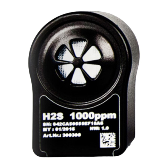
Page 30: Device Labelling
The specifications in this manual only apply to variants of the BLE Sensor module detailed in chapter "Technical data" on page 15. The type plate of the BLE Sensor module is located on the bottom of the module and contains the following specifications:... -
Page 31: Installation Of Spare And Wear Parts
5.11 Storage of the product The BLE Sensor module comprises no special transport mode. The capacity of the installed batteries is dimensioned in such a way that the max. service life of the sensor (1-3 years depending on the type of sensor module) is covered. -
Page 33: Chapter 6 Functional Principle
BLE Sensor module The device is a portable measurement instrument approved for Ex zone 1 for determining gas concentrations. Current measurement values can be read out of the BLE Sensor module via the Bluetooth connection (Bluetooth Low Energy). "GasBuster" smartphone app When combined with a Bluetooth Low Energy compatible smartphone, the "GasBuster"... -
Page 34: Determining The Gas Concentration
6.1 Determining the gas concentration Diagram of how the "Gas" measurement value is generated 1 Determining the raw value (see "Determining the 3 Conversion of the calibrated gas measurement raw value" on page 34) value to the trimmed gas measurement value (see "Calculation of the trimmed gas measurement value"... -
Page 35: Calculation Of The Calibrated Gas Measurement Value
Chapter 6 Functional principle 6.1.2 Calculation of the calibrated gas measurement value The raw value determined during the previous step is converted into the gas measurement value by means of the slope and offset determined during the calibration (see "Calibration process" on page 65). Min. -
Page 36: Calculation Of The Trimmed Gas Measurement Value
6.1.3 Calculation of the trimmed gas measurement value The calibrated gas measurement value determined during the previous step can also be slightly adjusted (trimmed) during this step. For this purpose, the determined slope and offset are used for the trimming process (see "Trimming"... -
Page 37: Chapter 7 Storage, Delivery And Transport
An RMA number is mandatory for any returns and can be obtained from the Support & Service Centre (see "Contact information" on page 83). The return shipment of the BLE Sensor module must occur in the original packaging and with freight and insurance paid to Microtronics Engineering GmbH (see "Contact information"... -
Page 39: Chapter 8 Installation
8.1 Dimensions Dimensions: Depth Dimensions: Width and height 8.2 Installing the BLE Sensor module Important note: Ensure installation is completed correctly. Comply with existing legal and/or operational directives. Improper handling can cause injuries and/or damage to the instruments. -
Page 40: Inserting The Sensor Module In A Data Logger
8.2.1 Inserting the sensor module in a data logger When using the BLE Sensor module in conjunction with a compatible data logger, the module is inserted in the sensor recess of the logger as illustrated in the following figure. It is designed in such a way that it cannot be inserted incorrectly. -
Page 41: Electrical Installation
"DeviceConfig " on page 45. It can be downloaded free of charge from the following website: www.microtronics.com/deviceconfig Chapter "GasBuster" on page 59 provides a detailed explanation of the "GaugeBuster" smartphone app. It is available for Android and iOS devices and can be downloaded free of charge from "Google Play" (Android) or the Apple "App Store"... -
Page 43: Chapter 9 Initial Start-Up
(Bluetooth Low Energy) and displayed using the "GasBuster" smartphone app (see "GasBuster" on page 59). We still recommend that the BLE Sensor module is first placed into operation in the office before moving the device to the place of use. Take the opportunity to get to know the functions of the device in a stable environment. -
Page 45: Chapter 10 Deviceconfig
10.1 General The DeviceConfig configuration program can be downloaded free of charge from the following website: www.microtronics.com/deviceconfig The tool is used for configuration, maintenance, fault analysis and synchronisation purposes. It is compatible with all myDatanet devices equipped with a USB interface, wireless M-bus interface or Bluetooth Low Energy. -
Page 46: Functional Principle
10.3.1 USB BLE-Adapter The USB BLE-Adapter (300685) is not included in the scope of delivery of the BLE Sensor module . It is required because standard PCs and laptops often do not have a Bluetooth Low Energy interface that is necessary for communication with the BLE Sensor module . -
Page 47: Installation
The following chapter describes the installation process in Windows 7. 1. Execute the "InstDeviceConfig.exe" file to start the installation process. Note: Only connect the device or USB BLE-Adapter (300685) to your PC once the installation process has completed as the required drivers are only installed during this process. - Page 48 Installation of the USB drivers for the devices Installation of the drivers for the USB BLE-Adapter Installation of the USB drivers for the devices on a M1 basis Installation of the USB drivers for the devices on a M2/M3 basis...
-
Page 49: Installing The Drivers For The Usb Ble-Adapter
3. Connect the USB BLE-Adapter (300685) to a free USB port on your PC. From Windows Vista onwards, the driver will be installed automatically. Instructions on installing the driver on older versions of Windows are included in the user manual for the DeviceConfig ("myDatanetDeviceConfig Manual "... -
Page 50: Menu Of The Deviceconfig
"Settings" menu item 10.5.1.1 Options The settings for the COM ports to which the USB radio transmitter (206.657) or the USB BLE-Adapter (300685) are connected can be specified and the automatic search for the available firmware versions can be activated or deactivated via the "Settings -> Options" menu item. -
Page 51: Establishing A Connection To A Sensor Module With Bluetooth Low Energy Interface
10.6 Establishing a connection to a sensor module with Bluetooth Low Energy interface The USB BLE-Adapter (300685) is required to establish a connection to a sensor module with a Bluetooth Low Energy interface. First of all complete the steps described in chapter "Installing the drivers for the USB BLE-Adapter "... - Page 52 Note: To ensure a stable connection, the wireless signal level should be higher than -90dBm , i.e. for example -85dBm . This is achieved by reducing the distance between the sensor module and the USB BLE-Adapter , and avoiding obstacles such as walls and similar. Rev. 03...
-
Page 53: Firmware" Tab
10.7 "Firmware" tab This tab enables firmware to be installed directly via the Bluetooth Low Energy interface. "Firmware" tab 1 Currently installed software version 2 Button to install a previously downloaded firmware package Rev. 03... -
Page 54: Trim" Tab
10.8 "Trim" tab DANGER: Extreme caution is required when handling calibration gases! If you are under the impression that based on the operational demands, the calibration of the sensor is no longer entirely correct, this can be compensated by the trimming process. This means that the time until the next scheduled calibration can be bypassed. - Page 55 "Trim" tab 1 Gas measurement value (calculated with the 7 Detected slope currently valid values for the offset and slope) 2 Upper reference point (target value in ppm) 8 Checkbox to display the input fields for the manual input of the trim 3 Lower reference point (target value in ppm) 9 Button to remove the trim 4 Button for adopting the lower reference point...
-
Page 56: Calibration" Tab
10.9 "Calibration" tab DANGER: Extreme caution is required when handling calibration gases! The "Calibration" tab enables the calibration of the sensor module that must be completed every 6 months at the latest. Note: The calibration must only be completed by a restricted group of people. A password is therefore required to access this tab. - Page 57 "Calibration" tab 1 Lower reference point (target value in ppm) 8 Button for adopting the upper reference point (gas) 2 Upper reference point (target value in ppm) 9 Raw value (temperature) 3 Raw value (gas) 10 Temperature measurement value (calculated with the currently valid values for the offset) 4 Gas measurement value (calculated with the 11 Offset for calculating the temperature...
-
Page 59: Chapter 11 Gasbuster
Chapter 11 GasBuster Chapter 11 GasBuster 11.1 General The "GasBuster" smartphone app is available for Android and iOS devices and can be downloaded free of charge from "Google Play" (Android) or the Apple "App Store" (iOS). The tool is designed to display the current values. The "GasBuster" smartphone app is compatible with all variants of the sensor module (see "Sensor modules"... -
Page 60: Overview
11.4 Overview Start screen The "GasBuster" smartphone app can be used to communicate with all variants of the BLE Sensor module (see "Sensor modules" on page 77). "Swipe" horizontally to switch between the identified devices and sensor modules. If the connection to the currently selected device or sensor module is interrupted, the next detected device or sensor module is selected after 15 seconds. - Page 61 6 Each point symbolises a detected device or "BLEGW" if it is a variant of a sensor module. The current selection is myDatasensH2S1000 BLE represented by the dark point. 3 Serial number of the detected device or sensor module (only the last 7 to 9 digits are displayed for...
-
Page 63: Chapter 12 Maintenance
Regularly check the BLE Sensor module for mechanical damage. Clean the BLE Sensor module with a soft, moist cloth. Use a mild cleaning agent, if necessary. Important note: Due to the electrostatic effects, the BLE Sensor module must not be rubbed with cloths in the Ex zone. -
Page 64: Safety Instructions For Handling H2S Gas
12.2.1.1 Safety instructions for handling H2S gas DANGER: Extreme caution is required when handling calibration gases! Hydrogen sulphide is a neurotoxic substance that can cause poisoning and even death depending on the concentration. It has the following effects on humans: ~ 0.1ppm: Odour threshold from 20ppm: Corneal damage following prolonged exposure approx. -
Page 65: Calibration Process
"Installation" on page 47. DeviceConfig 3. Connect the sensor module to the PC using the USB BLE-Adapter (300685) (see "Establishing a connection to a sensor module with Bluetooth Low Energy interface" on page 51). 4. The calibration must only be completed by a restricted group of people. A password is therefore required. - Page 66 6. Ensure that 0 ppm is selected for the lower reference point. Wait one minute before pressing the button to set the lower reference point. You can use the timer integrated in the interface to determine the amount of delay that remains. An acoustic signal is issued once the timer has elapsed. During this one- minute delay, it must be ensured that the gas concentration in the calibration room is 0 ppm (extraction active and all of the valves on the gas cylinders are closed).
- Page 67 Chapter 12 Maintenance 7. Place the sensor module in the Calibration adapter for BLE sensor module (300665), which should already be connected to the gas extraction station. Inserting the sensor module in the calibration adapter 1 Hose to the gas extraction station...
- Page 68 Dialogue window to enter additional information Device Type Not required for this device class Customer Name of the customer Customer no. (ERP) AB/RMA no. ERP number of the Order number or RMA number that the device is assigned to customer Gauger Name of the gauger who completed the calibration.
-
Page 69: Trimming
Chapter 12 Maintenance Path for signatures Folder where the PDFs with the digitised signatures of the Opens a dialogue window gaugers are located. to select the folder Last cal: Time of the last calibration (set automatically, although it can be edited) Next cal: Time when the next calibration should be completed (suggested automatically, although it can be edited) - Page 70 "Installation" on page 47. DeviceConfig 3. Connect the sensor module to the PC using the USB BLE-Adapter (300685) supplied (see "Establishing a connection to a sensor module with Bluetooth Low Energy interface" on page 51). 4. The trimming process can only be completed by a restricted group of people. A password is therefore required.
- Page 71 Chapter 12 Maintenance 6. Ensure that 0 ppm is selected for the lower reference point. Wait one minute before pressing the button to set the lower reference point. During this one minute, it must be ensured that no gas reaches the sensor.
- Page 72 7. Place the sensor module in the Calibration adapter for BLE sensor module (300665), which should already be connected to the source of the calibration gas. Inserting the sensor module in the calibration adapter 1 Hose to the source of the calibration gas...
-
Page 73: Chapter 13 Removal/Disposal
The device includes a battery or rechargeable battery (lithium) that must be disposed of separately. Depleted BLE Sensor module can also be returned to the manufacturer to be disposed of correctly (see "Contact information" on page 83). -
Page 75: Chapter 14 Troubleshooting And Repair
14.1 General problems Problem Cause/solution Communication problems (between Reduce the distance between the BLE Sensor module and BLE Sensor module and smartphone) the smartphone, and try to avoid obstacles such as walls and similar. The capacity of the battery pack is virtually depleted. -
Page 77: Chapter 15 Spare Parts And Accessories
Chapter 15 Spare parts and accessories Chapter 15 Spare parts and accessories 15.1 Sensor modules Measurement Description Quantity Order number range C2H4O 7ETO Sensor module 0-20ppm upon request CL2 7CLH Sensor module 0-20ppm 300899 CO 7E Sensor module 0-1000ppm upon request CO 7E/F Sensor module 0-1000ppm upon request... -
Page 78: Data Loggers
Quantity Order number MDN Magnet 206.803 Calibration set H2S 30ppm 206.810 Calibration set NH3 50ppm 206.811 Caliration gas H2S 30ppm 206.812 Calibration gas NH3 50ppm 206.860 DeviceConfig 300264 Calibration adapter for BLE sensor module 300665 USB BLE-Adapter 300685 Rev. 03... -
Page 79: Chapter 16 Document History
Chapter 16 Document history Chapter 16 Document history Rev. Date Changes 20.03.2017 First version 21.03.2017 Chapter "Device labelling" on page 30 Type plate updated 21.03.2017 The translation has been revised (grammar, wording,...) 10.10.2019 Chapter "Declaration of conformity" on page 7 Declaration of conformity updated Kapitel "Technical data"... -
Page 81: Chapter 17 Glossary
Chapter 17 Glossary Chapter 17 Glossary NaN value The myDatanet uses special encoding to display different error statuses in the measurement values, for example. By setting a measurement value to "NaN", it is clearly marked as invalid and is thus not used for any further calculations. -
Page 83: Chapter 18 Contact Information
Chapter 18 Contact information Chapter 18 Contact information Support & Service: Microtronics Engineering GmbH Hauptstrasse 7 3244 Ruprechtshofen Austria, Europe Tel. +43 (0)2756 7718023 support@microtronics.com www.microtronics.com Microtronics Engineering GmbH (Headquarters) Hauptstrasse 7 3244 Ruprechtshofen Austria, Europe Tel. +43 (0)2756 77180 Fax. - Page 84 Certified by TÜV AUSTRIA: EN ISO 9001:2015, EN ISO 14001:2015, EN ISO 50001:2011 for myDatanet | TÜV SÜD: ATEX Directive 2014/34/EU © Microtronics Engineering GmbH. All rights reserved. Photos: Microtronics Microtronics Engineering GmbH | www.microtronics.com Hauptstrasse 7 | 3244 Ruprechtshofen | Austria | +43 2756 77180 | office@microtronics.com 300792 | Rev.03...
Need help?
Do you have a question about the BLE and is the answer not in the manual?
Questions and answers