Table of Contents
Advertisement
Quick Links
User Manual
for
Amron International Diving Supply, Inc.
Model 8895-AMP-8
Model 8895-AMP-16
Entertainment Amplifier
S/N__________________
This manual and the information contained herein are provided for use as an operation
and maintenance guide. No license or rights to manufacture, reproduce, or sell either the
manual or articles described herein are given. Amron International Diving Supply, Inc.
reserves the right to change specifications without notice.
Amron International Diving Supply, Inc
1380 Aspen Way, Vista, California 92081 U.S.A
Phone (760) 208-6500 Fax (760) 599-3857
Email: Sales@amronintl.com
Web : www.amronintl.com
Copyright @ 1998, Amron International, Inc.
Revised October 2010
Advertisement
Table of Contents

Related Manuals for Amron 8895-AMP-8

Summary of Contents for Amron 8895-AMP-8
- Page 1 This manual and the information contained herein are provided for use as an operation and maintenance guide. No license or rights to manufacture, reproduce, or sell either the manual or articles described herein are given. Amron International Diving Supply, Inc. reserves the right to change specifications without notice.
-
Page 2: Table Of Contents
Electrical ........................1.1 Power ..........................1.2 Mechanical ........................1.3 Size ..........................1.4 General Information General Information ......................2.1 Figure 1 Picture 8895-AMP-8..................2.2 Figure 2 Picture 8895-AMP-8 (rear)................2.3 Options and Accessories Accessories........................3.1 Warranty and Service Policy Limited Warranty ......................4.1 Service Policy........................4.2 Controls and Connections Controls and Connections ....................5.1 Installation and Operation Operation ........................6.1... - Page 3 Cable Assembly Model 8895-600 ................9.10 Outside Junction Box Diagram Model 8895-700............9.11 Inside Junction Box Diagram Model 8895-800 ............9.12 Parts Identifier, Models 8895-AMP-8 & -16, Front ............9.13 Parts Identifier, Model 8895-AMP-8, Back ..............9.14 Parts Identifier, Model 8895-AMP-16, Back ..............9.15 Outside Junction Box Model 8895-700 ...............9.16 Parts Identifier, Model 8895-700 .................9.17...
-
Page 4: Specifications
SPECIFICATIONS ELECTRICAL Input Channels ..................... 4 Stereo Input Impedance (Each Input)................600 Ohms Frequency Response ................100 hz To 30 khz Sensitivity (Input)....................... 1 mV Output Channels ......................8 Output Power per Channel (RMS @ 8 Ohm Load)..........¼ Watts Output Impedance................Less Than 8 Ohms POWER A. -
Page 5: General Information
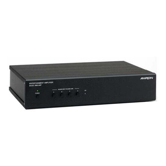
8895-AMP-8 and sixteen can be driven by the 8895-AMP-16. A 110/220 volt selector switch is located on the rear of both the Model 8895-AMP-8 & 8895-AMP- 16. Select the desired voltage by turning the sector switch with a small slotted screwdriver. - Page 6 GENERAL INFORMATION PICTURE OF THE MODEL 8895-AMP-8...
- Page 7 GENERAL INFORMATION PICTURE OF THE MODEL 8895-AMP-8 (rear)
-
Page 8: Accessories
Q. D.) Model 8895-600 Cable Assembly connects amplifier 8895-AMP-8 to outside junction box on chamber. Handles audio and channel selection signals for up to 8 patient entertainment modules. Two cable assemblies required for the 8895-AMP-16 amplifier unit. Cable Assembly is 20 feet long, other lengths available on special order. -
Page 9: Warranty And Service Policy
INTERNATIONAL DIVING SUPPLY, Inc. literature covering this product) for a period of 90 days from date of shipment. Amron's obligation under this warranty is limited to the repair or replacement of defective material at AMRON'S option. This warranty shall not cover defects which are the result of misuse, negligence, accident, repair or alterations. -
Page 10: Installation And Operation
INSTALLATION & OPERATION OPERATION Turn power on and confirm power is on by observing the power on indicator. Make sure all sources of audio are on and operating properly. On initial set up, set all volume controls on the source devices to minimum and all front panel volume controls to mid scale. -
Page 11: Installation
INSTALLATION & OPERATION INSTALLATION If you have purchased a complete system, begin by installing all components. The patient entertainment module should be installed in a convenient location for the patient to reach while seated in a normal position. Patient will need to be able to reach the yellow push button switch in order to change channels. -
Page 12: Theory Of Operation
THEORY OF OPERATION THEORY OF OPERATION The 8895-AMP-8 & 8895-AMP-16 are built in two configurations, an 8-patient and a 16-patient version. There are eight output audio amplifiers in the -8 and sixteen in the -16, each driving one patient entertainment module. Each of the amplifier’s inputs can be remotely controlled to select one of four input sources of audio. -
Page 13: Functional Block Diagram
THEORY OF OPERATION FUNCTIONAL BLOCK DIAGRAM... -
Page 14: Maintenance
MAINTENANCE PERIODIC TESTS & CHECKS The patient entertainment module pressure integrity should be checked annually. This can be done without disturbing module. Remove the headset and pressurize the tubing line to the entertainment module with 10 PSI of air. The module should hold this pressure without loss for a period of 60 seconds. -
Page 15: General
DRAWINGS General The following drawings illustrate the electrical and mechanical details of the patient entertainment units. The corresponding parts lists for each drawing are detailed in the parts lists section, or are included as part of the drawing. Revisions When drawings are updated, information about changes is incorporated into a revision sheet. This revision sheet appears in the manual immediately after the drawings. -
Page 16: Schematic, Model 8895-Amp-8
DRAWINGS SCHEMATIC, MODEL 8895-AMP-8... -
Page 17: Schematic, Model 8895-Amp-16
DRAWINGS SCHEMATIC, MODEL 8895-AMP-16... -
Page 18: Schematic, Audio 1 & 2 8895-200 Pc Card
DRAWINGS SCHEMATIC, AUDIO 1 & 2 8895-200 PC CARD... -
Page 19: Schematic, Audio 3 & 4 8895-200 Pc Card
DRAWINGS SCHEMATIC, AUDIO 3 & 4 8895-200 PC CARD... -
Page 20: Schematic, Audio 5 & 6 8895-200 Pc Card
DRAWINGS SCHEMATIC, AUDIO 5 & 6 8895-200 PC CARD... -
Page 21: Schematic, Audio 7 & 8 8895-200 Pc Card
DRAWINGS SCHEMATIC, AUDIO 7 & 8 8895-200 PC CARD... -
Page 22: Schematic, Input Audio & Power 8895-200 Pc Card
DRAWINGS SCHEMATIC, INPUT AUDIO & POWER 8895-200 PC CARD... -
Page 23: System Interconnect Diagram Model 8895
DRAWINGS SYSTEM INTERCONNECT DIAGRAM MODEL 8895... -
Page 24: Cable Assembly Model 8895-600
DRAWINGS CABLE ASSEMBLY MODEL 8895-600 9.10... -
Page 25: Outside Junction Box Diagram Model 8895-700
DRAWINGS OUTSIDE JUNCTION BOX DIAGRAM MODEL 8895-700 9.11... -
Page 26: Inside Junction Box Diagram Model 8895-800
DRAWINGS INSIDE JUNCTION BOX DIAGRAM MODEL 8895-800 9.12... -
Page 27: Parts Identifier, Models 8895-Amp-8 & -16, Front
DRAWINGS PARTS IDENTIFIER MODEL 8895-AMP-8 & -16, FRONT 9.13... -
Page 28: Parts Identifier Model 8895-Amp-8, Back
DRAWINGS PARTS IDENTIFIER MODEL 8895-AMP-8, BACK 9.14... -
Page 29: Parts Identifier Model 8895-Amp-16, Back
DRAWINGS PARTS IDENTIFIER MODEL 8895-AMP-16, BACK 9.15... -
Page 30: Outside Junction Box Model 8895-700
DRAWINGS OUTSIDE JUNCTION BOX MODEL 8895-700 9.16... -
Page 31: Parts Identifier Model 8895-700
DRAWINGS PARTS IDENTIFIER MODEL 8895-700 9.17... -
Page 32: Inside Junction Box Model 8895-800
DRAWINGS INSIDE JUNCTION BOX MODEL 8895-800 9.18... -
Page 33: Parts Identifier Model 8895-800
DRAWINGS PARTS IDENTIFIER MODEL 8895-800 9.19... -
Page 34: Parts List
To Order Replacement Parts Contact: Amron International Diving Supply, Inc. 1380 Aspen Way, Vista, California, 92081 U.S.A. Telephone: (760) 208-6500 -- Fax: (760) 599-3857 Email: sales@amronintl.com... -
Page 35: Model 8895-Amp-8,Top Assembly
10.2 Item Part Number Description 1........ 8895-001 ............. Front panel 8895-AMP-8 & 16 2........ 8895-8-500 ..........Chassis & Rear Panel Assembly 3........ 2825R-002..........Lid Rack Mount, Top & Bottom 4........ 8895-2009 ..............LED, Green Pin point 5........ 517-SJ-5003 ............Rubber Bumper (Foot) 6........ -
Page 36: Model 8895-005, Pneumatic Headset For O2 Hood
10.5 WARNING: DO NOT attempt to open, service or repair Patient Entertainment Set, Model 8895-100 All repairs and servicing are to be sent to: Amron International 1380 Aspen Way Vista, CA 92081 MODEL 8895-600, CABLE ASSEMBLY, 20 FOOT LENGTH 10.6... -
Page 37: Model 8895-700, Junction Box, Outside
PARTS LISTS MODEL 8895-700, JUNCTION BOX (OUTSIDE) 10.7 Item Part Number Description 1........ MP-3125GC4-001 ............Cover, Junction Box 2........ 3125-052 ..............Bracket, Junction box 3........ 3127-003 ................Bushing, Female 4........ 28072-1-1 ............Penetrator, ¾” NPT Brass 5........ MS-3102A28-16S ........MS Connector, 20 Pin Female 6........ -
Page 38: Model 8895-8-500,Chassis & Rear Panel Assembly
PARTS LISTS MODEL 8895-8-500,CHASSIS & REAR PANEL ASSEMBLY 10.9 Item Part Number Description 1........ 8895-015 ..............Chassis Wrap Around 2........ 8895-007 ................Rail, Card Support 3........ 2825R-007............Bracket, Support Side Rail 4........ 8895-200A ..............P.C. Card Assembly 5........ MB2085SS2W30BA ......... Switch, Push Button DPDT 6........ -
Page 39: Model 8895-16-500,Chassis & Rear Panel Assembly
PARTS LISTS 10.10 MODEL 8895-16-500,CHASSIS & REAR PANEL ASSEMBLY Item Part Number Description 1........ 8895-015 ..............Chassis Wrap Around 2........ 8895-007 ................Rail, Card Support 3........ 2825R-007............Bracket, Support Side Rail 4........ 8895-200A ..............P. C. Card Assembly 5........ MB2085SS2W30BA ..........Switch, Push button DPDT 6........ -
Page 40: Model 8895-200A, Pc Card Assembly
PARTS LISTS MODEL 8895-200A, P.C. CARD ASSEMBLY 10.11 Designator Part Number Description ............PC8895A....PC-CARDAMPLIFIER 8895-8 AND 1 R58, 60 ..........29MF250-249.... RESISTOR 249 OHM 1% ¼ W MF R38, 44 ..........29SJ250-510..... RESISTOR 510 OHM 5% ¼ W R50,29,19,10,47,49,26, 28,16,18,7,9,36,39,42,45 ....
Need help?
Do you have a question about the 8895-AMP-8 and is the answer not in the manual?
Questions and answers