Table of Contents
Advertisement
Quick Links
Advertisement
Table of Contents

Related Manuals for HDI 2200


Summary of Contents for HDI 2200
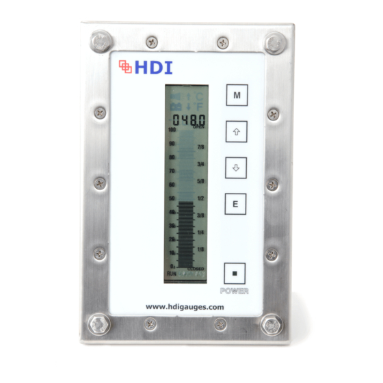
- Page 1 HDI 2200 Position Indicator Gauge User’s Manual Rev3...
-
Page 2: Table Of Contents
HDI 2200 Position Indicator User’s Manual – 2200, Rev 3 | JAN 2020 TABLE OF CONTENTS SECTION 1 Systems General Information: General Information: Unpacking and Inspection: Precautionary Information: Personnel Qualifications: SECTION 2 System Description: System Description General: System Components: 2.2.1 Position Indicator: 2.2.2 Position Sensors:... - Page 3 HDI 2200 Position Indicator User’s Manual – 2200, Rev 3 | JAN 2020 Preventative Maintenance SECTION 7 Choke Systems: Certification SECTION 8 Markings Reports SECTION 9 Warranty...
-
Page 4: Systems General Information
Systems General Information: General Information: This manual describes the installation operation and maintenance of the HDI #2200 Position Indicating System. This manual shall provide the user with information necessary to properly utilize the Position Indicating System. Included in this manual are all the necessary procedures to install and maintain this Position Indicating System Instrumentation properly. -
Page 5: System Description
SECTION 2 Systems Description: Systems Description: The HDI 2200 System is an Electronic Position Indicating System. The system consists of three (3) primary components as detailed in Section 2.2. An electronic potentiometer is housed in a stainless steel housing based on your specific choke body. The assembly is adjustable inside the housing to assure the sensor is located properly. -
Page 6: Remote Display
Remote displays may be provided to allow secondary indicators at an alternate location at the customer’s request. 2.4.2 4/20 mA Output: HDI offers as an option, a signal current loop providing a 4/20 mA remote output that may be used for chart recorder inputs and/or datalogging. 2.4.3 0-1VDC Output: HDI offers as an option, a signal providing a 0-1Vdc remote output that may be used by the customer for chart recorder inputs and/or datalogging. -
Page 7: Installation
Cables: All wire lengths from the Panel to the sensors shall be supplied by the customer. Prefabricated cables from HDI typically have the 3 Pin Male / 3 Socket Female connectors for quick installation. Mounting Hardware: Sensor integration to the choke bodies will generally use the existing bolts from the pneumatic sensors once removed, while the HDI sensors will be complete with all necessary hardware or adaptive stems as required for Swaco Rotary Sensors. - Page 8 ¼-20 screws, drop the gauge in the appropriate hole and replace the stopnuts. As part of our deliverables, HDI provides and rubber gasket that allows the LCD display to be dropped in from the front of the panel face or can be inserted from the back side based on your preference and serviceability.
-
Page 9: Theory Of Operation
HDI 2200 Position Indicator User’s Manual – 2200, Rev 3 | JAN 2020 SECTION 4 Theory of Operation: Positioning Systems: The major components of this system consist of the Control Head, Sensor, and interconnect Cable. The LCD (Control head) has an internal Power Source, a 3.6 potted (replaceable) Battery Pack that supplies power to the LCD via the power cable. -
Page 10: Position Systems
HDI 2200 Position Indicator User’s Manual – 2200, Rev 3 | JAN 2020 SECTION 5 CALIBRATION: Position System: THIS DEVICE IS CALIBRATED FROM THE POSITION INDICATOR (Display Panel) (SEE Section 4) 5.1.1 Setting Closed Position Level 1. Once the installation is complete the choke should be closed completely. -
Page 11: Position Systems Battery Replacement
It is suggested that you replace the desiccant pack, corrosion inhibitor and humidity indicator at this time. Reassemble the display which has the HDI 013 processor board assembly as one piece. If possible, it is suggested that you Test the System to ensure everything is working before closing up the gauge. - Page 12 HDI 2200 Position Indicator User’s Manual – 2200, Rev 3 | JAN 2020 SECTION 7 Preventative Maintenance: 7.1 Position Systems: This system does not require any user maintenance for day to day operation. The battery pack will need to be replaced on average every two (2) years.
- Page 13 HDI 2200 Position Indicator User’s Manual – 2200, Rev 3 | JAN 2020 SECTION 8 Certification: 8.1 Certification Markings: Gauge Head Sensor ATEX Certification Markings: Gauge Head Sensor Note: In the event one of the components (gauge or sensor) fails, you can order the replacement for a quick drop in replacement.
- Page 14 HDI 2200 Position Indicator User’s Manual – 2200, Rev 3 | JAN 2020 8.2 Certification Reports: CSA Report...
- Page 15 HDI 2200 Position Indicator User’s Manual – 2200, Rev 3 | JAN 2020 ATEX Report:...
- Page 16 | JAN 2020 SECTION 9 – Warranty HDI Instruments, LLC. (HDI) warrants this product for a period of one year from the date of shipment. HDI’s manufactured products to the extent that HDI will replace those parts having defects in material or workmanship when used for the purpose or specification HDI recommends for Normal Oilfield Usage.
- Page 17 HDI 2200 Position Indicator User’s Manual – 2200, Rev 3 | JAN 2020...
- Page 18 HDI 2200 Position Indicator User’s Manual – 2200, Rev 3 | JAN 2020 APPENDIX A WIRING INFORMATION: Input from Sensor: See listing under HDI 013 PCB in the table below: Sensor Wiring: Linear Potentiometer Device Markings Connector HDI 013 PCB Color Code...
- Page 19 HDI 2200 Position Indicator User’s Manual – 2200, Rev 3 | JAN 2020...
- Page 20 HDI 2200 Position Indicator User’s Manual – 2200, Rev 3 | JAN 2020 Client Maintenance Notes...
- Page 21 ISO 9001:2008 Office Phone - 713.688.8555 After Hours Support - 713.819.6103 Effective Sept 2016 4130 Directors Row Copyright 2016 Houston, TX 77092 Revision 1 | August 2016...
Need help?
Do you have a question about the 2200 and is the answer not in the manual?
Questions and answers