Table of Contents
Advertisement
Quick Links
Advertisement
Table of Contents

Related Manuals for HDI 2522


Summary of Contents for HDI 2522
- Page 1 HDI 2522 IECEX/ATEX POSITION INDICATOR GAUGE User’s Manual Rev A...
-
Page 2: Table Of Contents
Section 1 – Introduction .............................. 4 General Information ........................... 4 Unpacking and Inspection ........................4 Cautionary Information ..........................5 Section 2 – HDI 2522 Series Position Indicating Gauge Systems Overview ........6 System Overview ............................6 Accuracy ................................7 Control Head..............................7 Potentiometers .............................. - Page 3 HDI 2522 Position Indicator Gauge IECEX/ATEX User’s Manual – HDI 2522, Rev A | November,2019 Power Pack ..............................14 Processor Boards ............................15 Potentiometers ............................15 Section 7 – Troubleshooting ..........................15 Battery Voltage ............................15 Additional Troubleshooting ......................... 15 Section 8 - Installation Configurations ......................
-
Page 4: Section 1 - Introduction
The HDI 2522 has three key elements: the control head, a sensor assembly specified by the end client, and the cable assembly connecting the control head to the sensor assembly. These items will be discussed at greater detail in Section 2. -
Page 5: C Cautionary Information
Proper protection of the equipment should be a top priority when returning the equipment back to HDI or an authorized agent for repair. Additionally, it is the shipper’s responsibility to ensure equipment clears all customs as different agencies... -
Page 6: Section 2 - Hdi 2522 Series Position Indicating Gauge Systems Overview
The 2522 gauge system will enable the user to have either a 4-20mA output signal (as an added option) for chart recording or PLC integration or with the ability to have a slave gauge display to repeat the same position reading at a different location. -
Page 7: B Accuracy
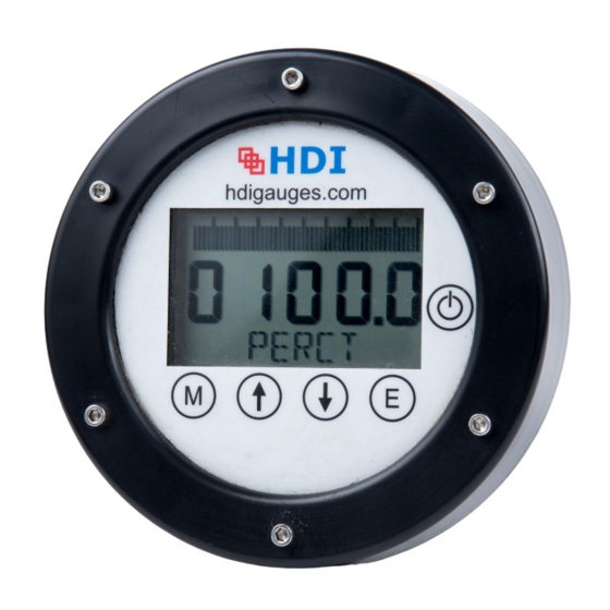
Control Head The HDI 2522 gauge has a 4-inch diameter LCD face providing a bar graph and is supplied with numeric digits at the bottom of the LCD for quick glance reading. Some adjustments may be necessary depending upon location and mounting methods to take into account deck lighting and overhead sunlight conditions. -
Page 8: E Cable
2.F.1 4-20 mA Output A current loop providing a 4-20 mA output is added as an option to the 2522 gauge system. This may be used for chart recorder inputs, data logging or PLC interface. This option requires that the 4-20 mA current loop be externally powered via customer supplied 12 or 24 Vdc. -
Page 9: G Certification
| November,2019 2.F.3 Remote/Slave Gauge Display The remote (“slave”) function utilizes the 0-1 Vdc output signal from the master 2522 gauge display. The slave gauge provides repeated gauge readout as displayed on the master unit. This is done utilizing only one potentiometer. The slave can be installed at any desired location and may also be installed with the 4-20 mA output option if required. -
Page 10: B Cables And Routing
CAUTION: It is extremely important to pay close attention to cable routing as to avoid noise sources that may impact gauge operation. HDI signal cable must be routed at least 6 inches from high voltage cable, 110 Volts and above. -
Page 11: B Gauge Head Features
HDI 2522 Position Indicator Gauge IECEX/ATEX User’s Manual – HDI 2522, Rev A | November,2019 Gauge Head Features As shown in the above figure, the gauge system has several distinctive features and functions that this manual will explain in following subsections. The buttons (M, ,E) and On/Off are part of the membrane panel and are discussed below. -
Page 12: I Up () Button
Section 5 – Gauge Operation Gauge Operation Overview The following sections will cover the two operational modes of the 2522 gauge: run mode and calibration mode. The run mode is the primary operating mode for the gauge. The calibration mode is utilized for gauge calibration. - Page 13 | November,2019 HDI keeps records on all the products it ships, and these records are filed by the serial number of the system. An additional feature of the 2522 gauge system is to be able to locate this serial number through the configuration mode.
-
Page 14: Section 6 - Maintenance
The customer will need to use a damp cloth to clean the gauge face or the gauge case. The gauge head should always be cleaned prior to opening the unit to prevent debris from entering the case. HDI recommends that the customer uses a soft cloth to prevent scratching to the protective lens. Power Pack The system is powered by an internal 3.6VDC power pack that is warranted for 12 months from the... -
Page 15: C Processor Boards
Warning: Low battery voltage will affect calibration. Processor Boards The 2522 gauge has two main internal boards, the LCD and the processor board. Both boards can be replaced in the field if either component has failed. The HDI LCD display board can be replaced without any requirements for calibration;... -
Page 16: Section 8 - Installation Configurations
IECEX/ATEX User’s Manual – HDI 2522, Rev A | November,2019 Commented [JG1]: Section 8 - Installation Configurations SOCKET TERMINAL DEFINITIONS A: 3 SOCKET = INLINE B: 3 PIN = 0-1V OUTPUT C: 5 PIN= 4-20ma OUTPUT 2522 Position Indicator Gauge with No Output Options... - Page 17 HDI 2522 Position Indicator Gauge IECEX/ATEX User’s Manual – HDI 2522, Rev A | November,2019 2522 Position Indicator Gauge with 0-1 Volt Output Option...
- Page 18 HDI 2522 Position Indicator Gauge IECEX/ATEX User’s Manual – HDI 2522, Rev A | November,2019 2522 Position Indicator Gauge with 4-20 mA Output Option...
- Page 19 HDI 2522 Position Indicator Gauge IECEX/ATEX User’s Manual – HDI 2522, Rev A | November,2019 2522 Position Indicator Gauge with a Primary/Secondary Option...
- Page 20 HDI 2522 Position Indicator Gauge IECEX/ATEX User’s Manual – HDI 2522, Rev A | November,2019 2522 Position Indicator Gauge Primary/Secondary with 0-1V...
- Page 21 HDI 2522 Position Indicator Gauge IECEX/ATEX User’s Manual – HDI 2522, Rev A | November,2019 2522 Position Indicator Gauge Primary/Secondary with 4-20 mA Output Option...
-
Page 22: Section 9 - Cable Connection Drawing
HDI 2522 Position Indicator Gauge IECEX/ATEX User’s Manual – HDI 2522, Rev A | November,2019 Section 9 - Cable Connection Drawing... -
Page 23: Section 10 - Gauge Mounting Diagram
HDI 2522 Position Indicator Gauge IECEX/ATEX User’s Manual – HDI 2522, Rev A | November,2019 Section 10 - Gauge Mounting Diagram... -
Page 24: Section 11 - Potentiometer Configurations
HDI 2522 Position Indicator Gauge IECEX/ATEX User’s Manual – HDI 2522, Rev A | November,2019 Section 11 – Potentiometer Configurations... - Page 25 HDI 2522 Position Indicator Gauge IECEX/ATEX User’s Manual – HDI 2522, Rev A | November,2019...
- Page 26 HDI 2522 Position Indicator Gauge IECEX/ATEX User’s Manual – HDI 2522, Rev A | November,2019...
-
Page 27: Section 12 - Certification Markings
HDI 2522 Position Indicator Gauge IECEX/ATEX User’s Manual – HDI 2522, Rev A | November,2019 Section 12 - Certification Markings ATEX / IECex Certification Markings: Gauge Head Certification Tag... -
Page 28: Section 13 - Iecex Certificate
HDI 2522 Position Indicator Gauge IECEX/ATEX User’s Manual – HDI 2522, Rev A | November,2019 Section 13 - IECEX Certificate... - Page 29 HDI 2522 Position Indicator Gauge IECEX/ATEX User’s Manual – HDI 2522, Rev A | November,2019...
- Page 30 HDI 2522 Position Indicator Gauge IECEX/ATEX User’s Manual – HDI 2522, Rev A | November,2019...
-
Page 31: Section 14 - Atex Certificate
HDI 2522 Position Indicator Gauge IECEX/ATEX User’s Manual – HDI 2522, Rev A | November,2019 Section 14 - ATEX Certificate... - Page 32 HDI 2522 Position Indicator Gauge IECEX/ATEX User’s Manual – HDI 2522, Rev A | November,2019...
- Page 33 HDI 2522 Position Indicator Gauge IECEX/ATEX User’s Manual – HDI 2522, Rev A | November,2019...
-
Page 34: Section 15 - Warranty
HDI and excluded from this warranty. This Warranty is non transferable and HDI shall not be liable for any damage, injury, loss to property or persons resulting from the use of any HDI's products or equipment whether such damage, injury or loss... - Page 35 HDI 2522 Position Indicator Gauge IECEX/ATEX User’s Manual – HDI 2522, Rev A | November,2019 Client Maintenance Notes...
- Page 36 ISO 9001:2015 Office Phone: 713.688.8555 After Hours Support, Primary: 713.446.2212 After Hours Support, Secondary: 713.819.6103 7240 Brittmoore Rd Suite #119 Houston, TX 77041...
Need help?
Do you have a question about the 2522 and is the answer not in the manual?
Questions and answers