Table of Contents
Advertisement
Quick Links
© Copyright 2015
EVERTZ MICROSYSTEMS LTD.
5292 John Lucas Drive
Burlington, Ontario
Canada L7L 5Z9
Phone:
+1 905-335-3700
Sales:
sales@evertz.com
Tech Support: service@evertz.com
Web Page:
http://www.evertz.com
Version 1.0, May 2015
The material contained in this manual consists of information that is the property of Evertz Microsystems and is intended solely for the use of
purchasers of the 1275T/1285T series product. Evertz Microsystems expressly prohibits the use of this manual for any purpose other than the
operation of the 1275T/1285T series product. Due to on going research and development, features and specifications in this manual are subject
to change without notice.
All rights reserved. No part of this publication may be reproduced without the express written permission of Evertz Microsystems Ltd. Copies of
this manual can be ordered from your Evertz dealer or from Evertz Microsystems.
1275T/1285T Series
Digital Clock Display
User Manual
Fax: +1 905-335-3573
Fax: +1 905-335-7571
Advertisement
Table of Contents

Subscribe to Our Youtube Channel
Related Manuals for evertz 1275T Series


Summary of Contents for evertz 1275T Series
- Page 1 Version 1.0, May 2015 The material contained in this manual consists of information that is the property of Evertz Microsystems and is intended solely for the use of purchasers of the 1275T/1285T series product. Evertz Microsystems expressly prohibits the use of this manual for any purpose other than the operation of the 1275T/1285T series product.
- Page 2 This page left intentionally blank...
- Page 3 IMPORTANT SAFETY INSTRUCTIONS The lightning flash with arrowhead symbol within an equilateral triangle is intended to alert the user to the presence of uninsulated “Dangerous voltage” within the product’s enclosure that may be of sufficient magnitude to constitute a risk of electric shock to persons. The exclamation point within an equilateral triangle is intended to alert the user to the presence of important operating and maintenance (Servicing) instructions in the literature accompanying the product.
- Page 4 WARNING Changes or Modifications not expressly approved by Evertz Microsystems Ltd. could void the user’s authority to operate the equipment. Use of unshielded plugs or cables may cause radiation interference. Properly shielded interface cables...
-
Page 5: Table Of Contents
1275T / 1285T Series Digital Clock Display TABLE OF CONTENTS OVERVIEW ........................... 1 INSTALLATION ..........................3 2.1. MOUNTING ........................... 3 2.2. CONNECTORS ........................4 2.2.1. Time Code Connectors ....................4 2.2.2. Ethernet Connections ....................4 2.2.3. Serial Port Connections ..................... 5 2.3. - Page 6 1275T / 1285T Series Digital Clock Display 5.2.3. Display ........................25 5.2.4. Daylight Saving Time ....................26 5.2.5. Control Port ......................27 5.3. IP SETTINGS ........................28 5.4. FAULT TRAPS ........................30 UPGRADE ..........................31 6.1. UPGRADE OVERVIEW ..................... 31 6.2.
-
Page 7: Digital Clock Display
Evertz products are for informational use only and are not warranties of future performance, either expressed or implied. The only warranty offered by Evertz in relation to this product is the Evertz standard limited warranty, stated in the sales contract or order confirmation form. - Page 8 1275T / 1285T Series Digital Clock Display This page left intentionally blank Page - iv REVISION HISTORY Revision 1.0...
-
Page 9: Overview
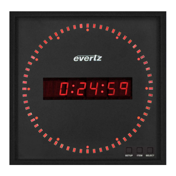
1275T / 1285T Series Digital Clock Display OVERVIEW The 1275T/1285T is a multifunction time-of-day display that can act as a slave to a master clock system or as a self-contained, pre-settable clock. Sixty bright rectangular LEDs are mounted in a circular arrangement simulating an analog second hand. -
Page 10: Figure 1-1 : 1275T/1285T Digital Clock
1275T / 1285T Series Digital Clock Display Figure 1-1 : 1275T/1285T Digital Clock Page - 2 OVERVIEW Revision 1.0... -
Page 11: Installation
1275T / 1285T Series Digital Clock Display INSTALLATION The following section describes the methods to mount and connect the device. 2.1. MOUNTING The 1275T/1285T is equipped with pre-fixed holes in the rear as depicted below in Figure 2-1. The clock can be mounted through screws on walls at the areas indicated by the arrows in the diagram. Figure 2-1: 1275T/1285T Rear Panel INSTALLATION Page - 3... -
Page 12: Connectors
1275T / 1285T Series Digital Clock Display 2.2. CONNECTORS The device comes with the ability to connect with other sources, in order to take time information, or configure & control the wall clock itself. This section provides describes the connection options to the device. -
Page 13: Serial Port Connections
1275T / 1285T Series Digital Clock Display Note the following cabling information for this wiring guide: • Only two pairs of wires are used in the 8-pin RJ 45 connector to carry Ethernet signals. • Even though pins 4, 5, 7 and 8 are not used, it is mandatory that they be present in the cable. •... -
Page 14: Power
1275T / 1285T Series Digital Clock Display 2.3. POWER The 1275T/1285T series displays come with an auto-ranging DC voltage adapter that automatically senses the input voltage. Power should be applied by connecting a 3-wire grounding type power supply cord to the power entry module on the DC voltage adapter. The power cord should be minimum 18 AWG wire size;... -
Page 15: Specifications
1275T / 1285T Series Digital Clock Display SPECIFICATIONS The following section stipulates the key specifications regarding the product’s hardware and software monitoring elements. Figure 3-1: 1275T/1285T Rear Panel 3.1. FUNCTIONAL SMPTE/EBU ST 12-2 LTC Time Code 20kΩ balanced or unbalanced or Code Input optional NTP DQS-B6 3.2. -
Page 16: Physical
1275T / 1285T Series Digital Clock Display 3.6. PHYSICAL Dimensions 1275T: 9.6” W x 9.6” H x 2.125” D (244mm W x 244mm H x 54mm D) 1285T 12.575”W x 12.575” H x 2.5” D (320mm W x 320mm H x 63mm D) Weight 5.0lbs (approx.) Mounting... -
Page 17: Operation
1275T / 1285T Series Digital Clock Display OPERATION The following section describes how to the 1275T/1285T functions and how to operate it in your environment. 4.1. AN OVERVIEW OF THE SETUP MENU SYSTEM The key to the operational flexibility of the 1275T/1285T series displays lies in the Setup menu system that provides a quick, intuitive method of configuring the display. -
Page 18: Front Panel Controls
1275T / 1285T Series Digital Clock Display To adjust any parameter, press the ITEM keys to adjust the parameter to its desired value. When you are showing the active value, the six large digits will flash on and off. When you have selected the desired parameter value press the SELECT key to make that value the active value. -
Page 19: Front Panel Displays
1275T / 1285T Series Digital Clock Display 4.2.2. Front Panel Displays The main LED display on the 1275T/1285T series displays consists of sixty LEDs around the outside of the face and a six character 16 segment alphanumeric display. In normal display modes the six digits are used to display the time or date. -
Page 20: Setting The Input Source
This is useful when the data had no date information since this looks like Legacy format date of January 1, 1980. When set to DQS the 1275T/1285T accepts Evertz DQS protocol timecode. When set to NONE, the 1275T/1285T series displays will free run on its internal crystal. -
Page 21: Setting The Time Daylight Saving Time Rules
1275T / 1285T Series Digital Clock Display 4.3.3. Setting the Time Daylight Saving Time Rules Daylight Saving Time (DST) or Summer Time as it is called in many countries, is a way of getting more daylight out of the summer days by advancing the clocks by one hour during the summer. Then, the sun will appear to rise one hour later in the morning when people are usually asleep anyway, at the benefit of one hour longer evenings when awake. -
Page 22: Table 4-2: Dst End Transition
1275T / 1285T Series Digital Clock Display How does the transition from DST end? Let's say that DST ends at 2:00 am local time and DST is one hour ahead of standard time: DST End Transition Local time DST or normal? Comments HH:MM:SS 00:59:59... - Page 23 1275T / 1285T Series Digital Clock Display Enables or Disables automatic application of Daylight Saving Time rules. Configures DST Date Entry Mode. Sets DST start month. Sets DST start week. Sets DST start day. Sets DST start hour. Sets DST end month. Sets DST end week.
- Page 24 1275T / 1285T Series Digital Clock Display 4.3.3.3. Setting the Beginning and End of Daylight Saving Time The four DST start registers (SH, SD, SM, SW) set the DST beginning time and the four DST end registers (EH, ED, EM, EW) set the DST end time. For the sake of simplicity only the DST start registers will be described, although they both operate in the same way.
-
Page 25: Selecting The Time Display Format
1275T / 1285T Series Digital Clock Display 4.3.4. Selecting the Time Display Format With this menu item, you can select whether the time information will be displayed in 12 hour or 24 hour format. 12 HR L 12 HR D When set to 12 HR L the time information will be displayed in 12 hour 24 HR L format. -
Page 26: Setting The Time
1275T / 1285T Series Digital Clock Display 4.3.6. Setting the Time With this menu item, you can set the time in the internal clock of the 1275T/1285T. Use the following procedure to set the time. You can press 00:00:00 the SETUP key at any time to exit the Set Time mode without affecting the clock time. -
Page 27: Setting The Internet Protocol And Ntp Rules
1275T / 1285T Series Digital Clock Display 4.3.8. Setting the Internet Protocol and NTP Rules The IC menu item, allows you to configure the Internet Protocol and NTP rules. When in IC menu, the two leftmost numeric displays show “IC”, and the alphanumeric display flashes the sub menu choice to indicate that there is another level of menus. - Page 28 1275T / 1285T Series Digital Clock Display 4.3.8.2. Internet Address Entry Procedure The following procedure is used to when setting the various IP addresses and net mask. IP addresses are entered in a decimal/dot format. For example, 192.205.22.5 or 255.255.255.0. Each number set between the dots represents 8 bits (‘octet’) of the IP address, and has a range of 0 to 255.
- Page 29 1275T / 1285T Series Digital Clock Display 4.3.8.3. Setting the Internet Address With this menu item, you can set the IP address used for static networks. See section 0 for IP setting instructions. The default is 10.0.0.1 xxx.yyy.zzz.aaa 4.3.8.4. Setting the Internet Net Mask With this menu item, you can set the IP net mask used for static networks.
- Page 30 1275T / 1285T Series Digital Clock Display 4.3.8.8. Setting the Trap Internet Address With this menu item, you can set the IP address that the 1275T/1285T will send traps to. xxx.yyy.zzz.aaa There are 4 IP addresses that can be set. This operates on the one pointed to by TS.
-
Page 31: Vistalink Pro Interface
1275T / 1285T Series Digital Clock Display ® VISTALINK PRO INTERFACE It is possible to completely configure and operate the 1275T/1285T on the network using our ® VistaLINK PRO interface. The device needs to be connected to a network through a LAN / Ethernet cable, and, manually, network information needs to be configured initially. -
Page 32: General
1275T / 1285T Series Digital Clock Display 5.2. GENERAL The general tab covers all key areas of configuration of the device. The individual settings can be seen in figure 5-2 and further explained in the tables below. Figure 5-2: General Settings Configuration 5.2.1. -
Page 33: Input
1275T / 1285T Series Digital Clock Display 5.2.2. Input Configuration Item Description Input Time Reference This setting selects input time reference. ntp should only be set when control optionNtp is set to ntpPresent The possible values that can be set are the following: •... -
Page 34: Daylight Saving Time
1275T / 1285T Series Digital Clock Display 5.2.4. Daylight Saving Time Configuration Item Description Automatic DST This setting enables automatic daylight saving time. DST Mode This setting selects the daylight saving time mode. Day of week of month selects a time such as: •... -
Page 35: Control Port
1275T / 1285T Series Digital Clock Display 5.2.5. Control Port Configuration Item Description IP Address This setting allows the definition DHCP mode or static IP mode. IP Netmask This setting allows the definition of the Netmask. IP Gateway This setting allows the definition of the Gateway. ®... -
Page 36: Ip Settings
1275T / 1285T Series Digital Clock Display 5.3. IP SETTINGS The IP Settings tab covers all the main network based settings of the device. The individual settings can be seen in figure 5-3 and further explained in the tables below. Figure 5-3: IP Settings Configuration ®... - Page 37 1275T / 1285T Series Digital Clock Display Configuration Item Description Trap IP Address 1 This setting allows the specification of a SNMP Trap IP address. It should be noted that specification of address should start with TAP IP Address 1, and onwards (to a max of 4) if further addresses are required.
-
Page 38: Fault Traps
1275T / 1285T Series Digital Clock Display 5.4. FAULT TRAPS Figure 5-4: Fault Traps Status Viewing Configuration Item Description Trap Enable – This enable traps to be sent to the trap addresses in the IP Settings tab. Loss of Reference Trap Status –... -
Page 39: Upgrade
Firmware Upgrade The firmware is considered the Operating System that runs the device. As Evertz keeps on improving capabilities of our devices, we will typically release new firmware for the device. The 1275T/1285T is upgraded through Serial port on the device an RS-232 Cable. -
Page 40: Vistalink Pro Upgrade Procedure
1275T / 1285T Series Digital Clock Display 6.2. VISTALINK PRO UPGRADE PROCEDURE ® This section discusses the approach to upgrading the configuration data on 1275T/1285T. Open VISTALINK PRO Server and navigate to Help > Apply Update > Product. ® Figure 6-1: How to Apply Update When the window opens you want to select the latest .jar file for the 1275T/1285T, from its saved location on the computer and select Open. -
Page 41: Figure 6-3: Module Dropdown Menu
® the 1275T/1285T module. The VISTALINK PRO Product Version reported in the top right corner of the window should match the new version. If it does not, please contact Evertz for further assistance. Figure 6-4: Version Information Window UPGRADE Page - 33... -
Page 42: Upgrade Firmware
1275T / 1285T Series Digital Clock Display 6.3. UPGRADE FIRMWARE This section explains how to upgrade the firmware of the 1275T/1285T through the Serial Port (or RS- 232). Important Note: Failure in the process of Firmware upgrade could result in the device becoming temporarily unusable. -
Page 43: Figure 6-6: Serial Connection Parameters
1275T / 1285T Series Digital Clock Display 6.3.1.2. Connecting the Terminal Application Open the terminal application (HyperTerminal / Tera Term etc.) Create a serial connection and ensure the following parameters have been set: Figure 6-6: Serial Connection Parameters It should be noted that the COM port can vary based on which port your serial cable is connected to and from computer to computer. -
Page 44: Figure 6-8: Rebooting Into Upgrade Mode
1275T / 1285T Series Digital Clock Display 6.3.1.4. Going into Upgrade Mode The device is active and running, awaiting commands at the serial prompt – command line interface (CLI). The next step is to turn the device into upgrade mode in order to send the firmware file to the device for the upgrade. -
Page 45: Figure 6-10: Select Binary File
1275T / 1285T Series Digital Clock Display Figure 6-10: Select Binary File The following screen, indicated by Figure 6-14 will be shown on your screen to display the transfer progress of the Figure 6-11: File Transfer in Progress UPGRADE Page - 37 Revision 1.0... -
Page 46: Figure 6-12: Reboot Screen
1275T / 1285T Series Digital Clock Display Once the file transfer is complete, the device will automatically reboot in order to reload. This reboot will be based on the new firmware that has been installed. Figure 6-12: Reboot Screen Page - 38 UPGRADE Revision 1.0...
Need help?
Do you have a question about the 1275T Series and is the answer not in the manual?
Questions and answers