
Subscribe to Our Youtube Channel
Related Manuals for Dahua DHI-ISC-EAA6000-P

Summary of Contents for Dahua DHI-ISC-EAA6000-P
- Page 1 User’s Manual EAS Acousto-Magnetic Antenna User’s Manual ZHEJIANG DAHUA VISION TECHNOLOGY CO., LTD. V1.0.0...
-
Page 2: Foreword
User’s Manual Foreword General This manual introduces the functions and operations of the EAS Acousto-Magnetic Antenna (hereinafter referred to as "the Device"). Models DHI-ISC-EAA6000-P DHI-ISC-EAA6000-R DHI-ISC-EAE0000-110 DHI-ISC-EAE0000-220 Safety Instructions The following signal words might appear in the manual. Signal Words... - Page 3 User’s Manual measures which include but are not limited: Providing clear and visible identification to inform people of the existence of the surveillance area and provide required contact information. About the Manual The manual is for reference only. Slight differences might be found between the manual and the ...
-
Page 4: Important Safeguards And Warnings
User’s Manual Important Safeguards and Warnings This section introduces the proper way of using the device, danger and property damage preventions. Before using the device, read this manual carefully. Follow the instructions and keep this manual properly for future reference. Operating Requirements Transport, use and store the device under allowed humidity and temperature conditions. -
Page 5: Table Of Contents
User’s Manual Contents Foreword ................................... II Important Safeguards and Warnings .........................IV 1 Overview ..................................1 Introduction ....................................1 Features and Advantages ............................... 1 2 Appearance ................................... 2 3 Installation and Configuration ..........................3 Cautions ......................................3 Packing List ....................................3 Installation and Configuration .............................. -
Page 6: Overview
User’s Manual Overview Introduction The development of information recognition technology has greatly improved the intelligence of commercial retail stores, helping to reduce labor costs and enhance economies of scale. The development and production of EAS technology have effectively improved logistics management and reduced the loss of merchandise. -
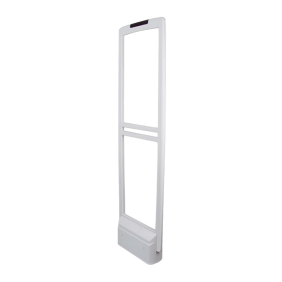
Page 7: Appearance
User’s Manual Appearance EAS Acousto-Magnetic Antenna is an advanced as well as software-driven Electronic Article Surveillance for shopping malls and supermarkets. It can overcome the influence of the environment and detect 58 KHz labels and tags. It has strong stability and high detection distance. The Acousto-Magnetic system includes a primary antenna with two replica antennas, no other controllers are needed, which makes installation in large supermarkets or multi-export venues very convenient. -
Page 8: Installation And Configuration
User’s Manual Installation and Configuration Cautions Only use for indoors, it is recommended to shut down the device during non-business hours. Do not cover the device and keep it ventilated. Pay attention to sun protection, waterproof and moisture-proof. ... -
Page 9: Installation And Configuration
User’s Manual Installation and Configuration 3.3.1 Preparations before You Begin Table 3-2 Tool requirements Name Image Name Image Phillips and M10×100 slotted expansion screw × screwdrivers Open-end Marker × 1 wrenches Cutting Hammer × 1 Machine × 1 Fine sand Scuff-plate Configuration Power drill ×... - Page 10 User’s Manual Install and fix the equipment: Put fine sand in the cutting groove to protect the cables and fill the gaps. Next install the scuff-plate on the floor. Then fix the equipment. The equipment installation is complete. ...
-
Page 11: Description Of Primary Antenna Tx Board Ports And Manual Configuration Of Hardware
User’s Manual 3.3.2 Description of Primary Antenna TX Board Ports and Manual Configuration of Hardware TX board ports Table 3-3 Description of TX board ports and manual configuration of hardware Port Function Settings By default, CH1 is for connecting RX board Use 9 Pin cable to connect, remember that CH1/CH2/CH3 of primary antenna;... - Page 12 User’s Manual Port Function Settings When the fault indicator is red, you can reset the system by the following steps. Take out a spare jumper and install it on J108-3&4. 1 Physical button for system Press the reset button once and wait RESET reset.
- Page 13 User’s Manual Port Function Settings J108-1&2: Turn off the transmission of the entire system. J108 You can choose to turn off 1&2= the transmission of the Transmission off system when the system is synchronizing with the ambient equipment. 3&4= J108-3&4: Factory reset Used in conjunction with —...
- Page 14 User’s Manual Port Function Settings The interpretation of the channel indicator is as follows: Working mode: The first one from the left in the first row is a working indicator. If the indicator flashes slowly, the program is under normal working conditions.
-
Page 15: Description Of Rx Board Ports And Manual Configuration Of Hardware
User’s Manual 3.3.3 Description of RX Board Ports and Manual Configuration of Hardware RX board ports Table 3-4 RX board ports and manual configuration of hardware Port Description Use 9 Pin cable to connect to CH1/CH2/CH3 of the TX board of primary antenna, remember that cold plug, electrical hot plug will cause damage to the TX board. -
Page 16: Software Debugging
User’s Manual JUMPER Spare jumper. Software debugging 3.4.1 Software Installation Install and debug software applications with software compression package Install and debug the module driver with driver compression package CH341SER.EXE. Check whether the installation of step1&2 is successful. Right-click on the computer desktop and select My Computer> Device Manager> Port. Use blue configuration cable to connect TX board and computer. -
Page 17: Interface Parameter Description
User’s Manual 3.4.2 Interface Parameter Description 3.4.2.1 Interface Parameter Software parameter Table 3-5 Interface parameter description Default Parameter Parameter Range Description Parameter Phase 0–119 Set the phase. 57.8 K/58 K/58.2 Frequency 58 K Change accordingly to the label’s frequency. K/58.4 K/58.6 K Change accordingly to the ambient Mode1/Mode2/Mode Tx Mode... - Page 18 User’s Manual Default Parameter Parameter Range Description Parameter Detect whether there is Jammer Detc around the antenna that maliciously interfere with the antenna's normal work. When a malicious signal is detected, the Jammer ON/OFF antenna indicator will "flash 4 Detc times—pause—flash 4 times—pause".
- Page 19 User’s Manual Sync interface Table 3-6 Description of sync interface parameters Parameter Description Environment System Phase The red square indicates the situation of signal transmission. The black square indicates the surrounding signal. It’s convenient Surrounding Signal to use the mouse to calculate the phase differences between antenna system and peripherals.
- Page 20 User’s Manual Parameter Description Click Display, and the antenna will automatically upload the Display channel signal and background noise. Click Stop after debugging. The obtained phase will be transmitted Stop to the system through the parameter setting interface and saved. Switch Left and Right in the debug phase.
- Page 21 User’s Manual Phase difference calculation Enter the obtained phase difference value into Phase in Parameter Setting and click Set and Save. If you observe that the noise and signal displayed by the channel signal are the smallest, it means phase synchronization is completed. Phase sync...
- Page 22 User’s Manual 3.4.2.4 Alarm Records Alarm records view Table 3-7 Alarm parameter description Parameter Description Record Type CH1/CH2/CH3 Alarm Corresponding to alarm record of the signal channel. Hour Tick After the system is powered on, this record will be automatically generated every hour.
- Page 23 User’s Manual Channel widths: About 1 m–2 m One primary antenna Channel widths: About 2 m–4 m One primary and one replica antennas Channel widths: About 4 m–6 m One primary and two replica antennas Channel widths: About 6 m–8 m ...
- Page 24 User’s Manual Channel widths: About 8 m–10 m Two primary and three replica antennas By analogy, one primary antenna can work with two replica antennas, and the primary antenna can also work alone, which can greatly meet the requirements of different channel widths.
-
Page 25: Cybersecurity Recommendations
User’s Manual Cybersecurity Recommendations Cybersecurity is more than just a buzzword: it’s something that pertains to every device that is connected to the internet. IP video surveillance is not immune to cyber risks, but taking basic steps toward protecting and strengthening networks and networked appliances will make them less susceptible to attacks. - Page 26 User’s Manual We suggest you to change default HTTP and other service ports into any set of numbers between 1024~65535, reducing the risk of outsiders being able to guess which ports you are using. Enable HTTPS We suggest you to enable HTTPS, so that you visit Web service through a secure communication channel.
- Page 27 User’s Manual Enable IP/MAC address filtering function to limit the range of hosts allowed to access the device.
Need help?
Do you have a question about the DHI-ISC-EAA6000-P and is the answer not in the manual?
Questions and answers