Table of Contents
Advertisement
Quick Links
Advertisement
Table of Contents

Related Manuals for Tar River DRL-072

Summary of Contents for Tar River DRL-072
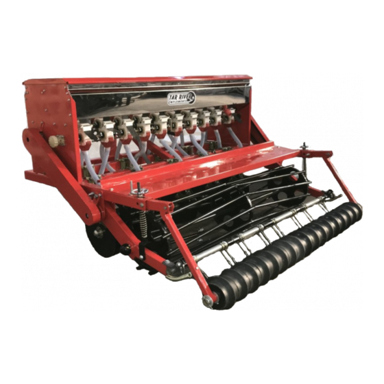
- Page 1 DRL-072 CROP SEEDER Operator’s Manual March 2019...
-
Page 2: Table Of Contents
TABLE OF CONTENTS INTRODUCTION ……………………………………………………………………………………………1 SAFETY ………………………………………………………………………………………………………….1 SAFETY SIGNAL WORDS ……………………………………………………………………………….2 GENERAL SAFETY GUIDELINES …………………………………………………………………. ..2 SAFETY DECAL CARE …………………………………………………………………………………….3 BEFORE OPERATION …………………………………………………………………………………….3 DURING OPERATION …………………………………………………………………………………. ..4 HIGHWAY AND TRANSPORT OPERATIONS ……………………..……………………………5 IMPORTANT INSTRUCTIONS BEFORE FIRST USE …….……….………………………….7 ASSEMBLY………………………………………………………………………………………………...8-10 SEED FERTILIZER….………………………………………………………………………………...11-12 PARTS BREAKDOWN……………………………………………………………………………….14-35... -
Page 3: Introduction
INTRODUCTION Thank you for purchasing your DRL-072 Crop Seeder. The DRL-072 is designed to be used in pre- pared seeding conditions. It is not intended as a No-Till Drill. It is important to properly maintain and keep in place all safety guards and shields that came with your Machine. -
Page 4: Safety Signal Words
SAFETY SIGNAL WORDS Note the use of the signal words DANGER, WARNING and CAUTION with the safety messages. The appropriate signal word for each has been selected using the following guidelines: DANGER: Indicates an imminently hazardous situation that, if not avoided, will result in death or serious injury. -
Page 5: Safety Decal Care
SAFETY DECAL CARE • Keep safety signs clean and legible at all times. • Replace safety signs that are missing or have become illegible. • Replaced parts that displayed a safety sign should also display the current sign. • Safety signs are available from your Distributor or Dealer Parts Department or the factory. How to Install Safety Signs: •... -
Page 6: During Operation
• Don’t hurry the learning process or take the unit for granted. Ease into it and become familiar with your new equipment. • Practice operation of your equipment and its attachments. Completely familiarize yourself and other operators with its operation before using. •... -
Page 7: Highway And Transport Operations
• DO NOT operate near the edge of drop-offs or banks. • DO NOT operate on steep slopes as overturn may result. • Operate up and down (not across) intermediate slopes. Avoid sudden starts and stops. HIGHWAY AND TRANSPORT OPERATIONS •... - Page 8 • Watch for obstructions overhead and to the side while transporting. • Always operate equipment in a position to provide maximum visibility at all times. Make allowances for increased length and weight of the equipment when making turns, or stopping the unit, etc.
-
Page 9: Important Instructions Before First Use
Introduction It is important that you read the entire manual to become familiar with this product before you begin using it. This product is designed for certain applications only. The manufacturer cannot be responsible for issues arising from modification. We strongly recommend this product not be modified and/or used for any application other than that for which it was designed. -
Page 10: Assembly
Assembly 1. Support frame a few feet above floor with blocks or a Tar River Implement handler. 2. Bolt on coulter assemblies using the U-bolts closed end facing the three point, using the last two bars. Off set the drills as evenly as possible 5 on one bar 5 on the next bar. - Page 11 7. Install Cage Roller on both Roller Arms. Ensure Grease Fitting is to the outside. Secure in place with nuts and cotter pins. 8. Install lower arm brackets onto frame 4 total 2 on each side as well as smaller sprocket screw side facing out. 9.
- Page 12 SOWING DEPTH CONTROL Move up to raise sowing depth Move up to reduce sowing depth • The Sowing Depth Control Device makes the seeder keep the same seeding depth during use. • The Rear Roller will power the chain and the gear. The coulter will open the soil, the seed box will drop the seed and the cover plate will close the soil.
-
Page 13: Seed Fertilizer
Note the following in order to avoid fertilizer burn: The fertilizing rate should be controlled according to your field condition. Choose the proper fertilizer for the seed. Always inspect, maintain or adjust the seeder after each use. While operating the seeder, keep area clean, free of clutter and well lit. Keep children and bystanders away. Distractions can cause you to lose control, so bystanders should remain at a safe distance from the work area. - Page 14 Weight, size, relative humidity, and moisture content can affect seeding rates. Users can adjust the position of the seed/fertilizer tongue and lock in different positions by moving the cotter pin to meet the different seeding/ fertilizing size. SEEDING/FERTILIZING RATE ADJUSTMENT HANDLE To adjust the fertilizer rate, you will need to adjust hand wheels (on each side of hopper).
- Page 15 NOTES...
- Page 17 Position Part # Description DL1001 Fertilizer/Seed Box Lid DL1002 Box Support Bar DL1003 Box Bottom FBM061016 Flanged Bolt - M6 x 1.0 x 16 All locations - 51 FNM061 Flanged Nut - M6 x 1.0 All Locations - 51 D1224 Decal–...
- Page 18 Right Side Left Side...
- Page 19 Position Part # Description FBM061016 Bolts (on right or left side) FNM061 Flanged Nut– M6 x 1.0 DL2003 Right Side Chain Sprocket DL2004 Seed box Side (Right) DL2005 Adjustment Handle Assembly DL2006 Left Side Chain Sprocket DL2007 Seed Box Side (Left) DL2008 Seed Adjustment Shaft DL2009...
- Page 21 Position Part # Description DL3001 Fertilizer/Seed Tubes (Needs Cut to 470M) DL3002 Seed Tubes (Needs Cut to 533M) These are the same hoses but the lengths need to be cut as specified. DL3003 Chain- Left Side DL3004A Chain– Right Side 55MM Sprocket Small Link DL3004B Chain–...
- Page 23 Position Part # Description DL4001 Support Frame DL4002 Cultipacker Roller Arm DL4003 Support Arm BM12175100 Bolt - M12 x 1.75 x 100 NM12175 Nut - M12 x 1.75 FW12 Washer DL4007 Pin M12 x 54 CP3x25 Cotter Pin M3 x 25 BM0812550DE M8 x1.25 x50 Drilled End NM08125 Nut - M8 x 1.25...
- Page 25 Position Part # Description DL5001 Lid Bracket (Left Side) DL5002 Lid Bracket (Right Side) DL 5003 Lid Piston BM0812540 Bolt NM08125 FBM061016 Bolt– M6 x 1.0 x 16 FNM0610 Nut– M6 x 1.0 BM0812516 Bolt- NM08125...
- Page 26 14 15 3 4 5 14 15 11 12 13...
- Page 27 Position Part # Description DL6001 Complete Cloture DL6002 U-bolt– M12 x 1.75 FW12 Flat Washer– M12 LW12 Lock Washer– M12 NM12175 Nut– M12 x 1.75 DL6006 Scraper Assembly– Inner DL6007 Scraper Assembly– Outer DL6008 Fender DL6009 Cloture Spring DL6010 Cloture Mounting Bracket DL6011 Shoulder Pin–...
- Page 29 Position Part # Description DL7001 Seed/Fertilizer Distribution Box DL7002 Complete Clamp Assembly CP3x70 Cotter Pin– M3 x 70 DL7004 Distribution Face Plate DL7005 Counter Pointer DL7006 Seed Cup DL7007 Waste/Seed/Fertilizer Flow Shutoff Flap...
- Page 30 12 15 11 13 14 20 16 17 18 19 2 20 14 12 15...
- Page 31 Position Part # Description DL8001 Handle Complete BM12175110 Bolt– M12 x 1.75 x 110 DL8003 Bracket DL8004 Spring DL8005 Small Gear Shaft DL8006 Down Pressure Adjustment DL8007 Drive Roller DL8008 LNM1620 Locking Nut– M16 x 2.0 DNM1620 Dome Nut– M16 x 2.0 (Optional) BM1217590 Flat Washer–...
- Page 33 Position Part # Description DL9001 Drive Roller Cultipacker Roller- (Doesn’t include DL9002 Arms) DL9003 Cultipacker Sections FW24 Flat Washer– M24 CP5x50 Cotter Pin– M5 x 50 DL9006 Cultipacker Shaft DL9007 Flap Shaft DL10012 Protective Cover GN081S Grease Nipple– M8 x 1.0 (Straight)
- Page 35 Position Part # Description DL10001 Step Board RT1004D Decal– Warning RT1004E Decal– Warning DL10004 Left Hand Chain Shield DL10005 Right Hand Chain Shield BM101580 Bolt– M10 x 1.5 x 80 NM1015 Nut– M10 x 1.5 LW10 Lock Washer– M10 DL10009 Protective Cover–...
- Page 36 5 7 13 14 2 3 4 6 7 8 12...
- Page 37 Position Part # Description DL11001 Down Force Spring NM1015 Nut– M10 x 1.5 FW10 Flat Washer– M10 LW10 Lock Washer– M10 BM0812545DE Drilled End Bolt– M8 x 1.25 x 45 LFW08 Large Flat Washer LW08 Lock Washer– M8 NM08125 Nut– M8 x 1.25 DL11009 Flap Spring DL11010...
Need help?
Do you have a question about the DRL-072 and is the answer not in the manual?
Questions and answers