Table of Contents
Advertisement
Quick Links
Advertisement
Table of Contents

Related Manuals for Organomation Associates N-EVAP 11106


Summary of Contents for Organomation Associates N-EVAP 11106
- Page 1 N-EVAP Nitrogen Evaporation System Models 11106, 11155, 11250 DRY BATH SYSTEMS INSTRUCTION MANUAL RGANOMATION SSOCIATES 266 RIVER ROAD WEST BERLIN, MA 01503 U. S. A. Tel: 888-838-7300 Fax: 978-838-2786 Email: sales@organomation.com...
- Page 3 If you need a verbal or written quote on specific items please call us at our toll free number or e.mail us at the address above. Again, thank you for selecting ORGANOMATION ASSOCIATES products. Sincerely, Andrew McNiven...
-
Page 5: Table Of Contents
N-EVAP TABLE OF CONTENTS Forward - Letter from the President Introduction Instrument Items Shipped Instrument Description Instrument Part Identification Installation Location Bath Setup Instrument Setup Safety Considerations - Read before operation Operation Instrument Control Identification Planning and Preparation Type Z Purge Positive Pressure Bath Option Bath Operation Instrument Operation Optimization... -
Page 6: Instrument Items Shipped
Contact Organomation Associates Inc. immediately if any damage or discrepancies are found. Your shipment should contain one or more of the instruments shown below. Option codes are listed on the next page. - Page 7 INTRODUCTION N-EVAP ™ Option Codes and additional items shipped The following list contains option codes and items which may have been shipped in conjunction with the standard parts shown on the previous page. Please check your packing list and order information carefully to determine if these items are included in your shipment. For a complete list of available accessories, please refer to the Accessories Section.
-
Page 8: Introduction
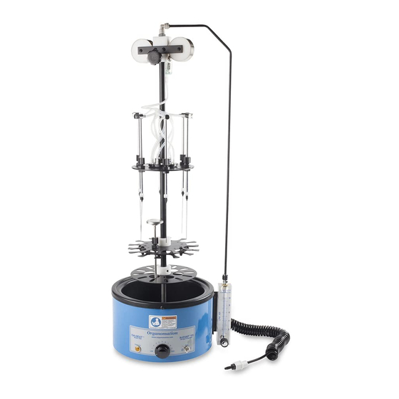
Phthalate free. Dry baths do not have the hoist assembly and band springs shown below. Only water baths have sample trays that can be raised and lowered. The complete instrument is shown below. Organomation Associates Inc. 266 River Road West Berlin, MA 01503... -
Page 9: Instrument Part Identification
INTRODUCTION N-EVAP ™ PARTS LIST Description Item 11250-DA Part Name 11106-DA 11155-DA B1201-DA Round dry bath, provides heat. Dry Bath B1102-DA B1102-DA P0614 Holds and centers samples. Sample Spring P0614 P0614 P0715 Holds various sized samples. Sample Holder NA1113 P0628 NA0403 Removes particles from gas stream. -
Page 10: Installation
INSTALLATION N-EVAP ™ Location The N-EVAP Evaporator System should be located on a bench top or in a chemical fume hood if hazardous or flammable materials and solvents are to be used. The location should provide the necessary support services for the instrument. These include electrical power (required for heating bath) and a clean inert gas source (Air or Nitrogen). - Page 11 INSTALLATION N-EVAP ™ Bath Setup(Continued) Fill the bath chamber with dry media. Dry media baths have a raised center section in the bath to the height of the rim. See diagram below. Dry bath units - Fill the area between the rim and the raised central section with aluminum or glass beads.
- Page 12 INSTALLATION N-EVAP ™ Bath Setup (Continued) Type-Z Purge Positive Pressure Bath option - If you do not have this option, please proceed to the next section. Procedures for operating this system may be found in the Operation Section. Quick start instructions are posted on the front of the bath.
- Page 13 INSTALLATION N-EVAP ™ Bath Setup (Continued) Flowmeter Assembly - Provided with all N-EVAP Systems. If an OA-HEAT bath was purchased without an N-EVAP instrument, proceed to the next section. Attach the flowmeter to the bracket mounted on the bath with the two 10/32 x 1/2”...
-
Page 14: Instrument Setup
INSTALLATION N-EVAP ™ Instrument Setup Place the instrument into the bath. Screw the rod into the raised center. Slide the instrument over the end of the rod. Model 112 has a split rod design. Connect the SS gas line as follows: Connect the lower end of the SS Gas Tube to the fitting on the top of the flowmeter. - Page 15 INSTALLATION N-EVAP ™ Instrument Setup (Continued) Raise all Valve Tubes to their highest position. The plastic tube nuts on the top plate should be adjusted so that the Valve Tubes slide easily by hand, but do not fall when released. Turn all needle valves on the Valve Tube Assembly off by rotating clockwise.
- Page 16 SAFETY N-EVAP ™ Safety Considerations READ THIS SECTION BEFORE EQUIPMENT OPERATION! This equipment is designed for use in the Analytical or Environmental Laboratory by trained laboratory personnel for evaporative applications. Use of this equipment beyond its stated intended purpose and operating parameters is not recommended and will be the sole responsibility of the user.
-
Page 17: Operation
OPERATION N-EVAP ™ Instrument Controls Toggle Switch - Located on the front right bath label. Turns power to the bath on and off. Thermostat Knob - Located on the front center bath label. Adjusts the bath temperature. Amber Light - Located on the front left bath label. -
Page 18: Bath Operation
OPERATION N-EVAP ™ Bath Operation Press the reset button on the GFCI (if present). Turn the bath toggle switch on. Thermostat Control - Adjust the bath thermostat to the desired temperature. N-EVAP dry bath maximum temperature 150°C. Allow the bath to heat to the desired temperature and stabilize V22.5 - 13 -... -
Page 19: Instrument Operation
OPERATION N-EVAP ™ Instrument Operation Place the test tubes with samples into the sample holder plate assembly. The positions are numbered for sample identification. The sample holder spring will hold the test tube firmly in place. The test tube bottom should be pressed into the dry media. Install the SS needles or pipets for the number of positions to be used. -
Page 20: Optimization
OPERATION N-EVAP ™ Instrument Operation (Continued) Continue the evaporation until complete. For non-dryness endpoint requirements, it will be necessary for a technician to monitor the evaporation and to remove the samples manually once the desired endpoint is reached. Refer to the next section for refinements and operating tips for these procedures. -
Page 21: Maintenance And Cleaning
MAINTENANCE N-EVAP ™ Maintenance and Cleaning The N-EVAP Evaporation system is manufactured from extremely durable materials and may last for years if operated and maintained properly. The following guidelines are recommended for use with N-EVAP systems. Cleaning - The stainless steel components may be cleaned with an abrasive or scouring pad followed by rinsing with clean water Teflon coated parts (black in color) should be cleaned with non-abrasive materials only, otherwise scratching will result and the coating will be... -
Page 22: Troubleshooting
TROUBLESHOOTING N-EVAP ™ SYMPTOMS CAUSES SOLUTIONS Reset light gray switch on GFCI. Contact factory for instructions. No Power to bath. Electrical outlet not energized. Bath will require service, contact Bath power cord not plugged in. factory for instructions. GFCI not reset. Internal electrical fault. -
Page 23: Service And Returns
Contact Organomation Technical Support Department Before returning any product to Organomation Associates for any reason, please contact the Technical Support Department, toll free at 888-838-7300 or email sales@organomation.com. Support is available free of charge to customers of Organomation in good standing for all products manufactured by Organomation. -
Page 24: Shipping - Claims For Damage Or Shortage
N-EVAP ™ Shipping - Claims for damage and shortage Organomation Associates Inc. makes a sincere effort to ensure your purchase is properly packed and all items listed on the packing slip are in fact enclosed with the shipment. In the event that your purchase is damaged or if any items are missing, please follow the procedures below. -
Page 25: Technical Information
TECHNICAL INFORMATION N-EVAP ™ Specifications Electrical Requirements: 120 or 240 VAC single phase, non switchable, 50 - 60 Hz. 3 wire grounded outlet required. GFCI (Ground Fault Circuit Interrupter) optional. Model 11106 & 11155 6 &12 Position Bath 500 W* Model 11250 24 Position Bath 800 W* * 240V units divide wattage by 2. - Page 26 PARTS LIST N-EVAP ™ Parts Identification Organomation Associates Inc. 266 River Road West Berlin, MA 01503 N-EVAP OA-SYS Heating System HEAT POWER HIGH Figure 8 V22.5 - 21 -...
- Page 27 PARTS LIST N-EVAP ™ Parts List (See Figure 2) Item Part Name Description On/Off Toggle Switch Turns on bath power. Thermostat adjustment knob Controls bath temperature. Amber heat light Indicates when bath is heating. Bath Feet Polypropylene, lifts bath from bench. Base Plate Sits in bath pan, holds instrument upright.
- Page 30 CE Declaration of Conformity Revised June 1, 2015 We, Organomation Associates Inc a corporation registered in Massachusetts, United States of America, declare under sole responsibility that the following equipment to which this declaration relates, meets the principal protection requirements and is in conformity with relevant sections of the applicable CE standards and other normative documents.
Need help?
Do you have a question about the N-EVAP 11106 and is the answer not in the manual?
Questions and answers