Table of Contents
Advertisement
Quick Links
Advertisement
Table of Contents

Related Manuals for Haefely AXOS

Summary of Contents for Haefely AXOS
- Page 1 AXOS Expandable test systems User Manual 4700924 | Version 2.2...
- Page 2 Revision History Version Date Author Remarks New layout, safety chapter adapted. Axos and Axos 09.02.2022 shared document New logos 13.12.2021...
- Page 3 Although all efforts are made to ensure that there are no errors in the manuals, HAEFELY accepts no responsibility for damage or loss that may result from errors within this manual. We retain the right to modify the functionality, specification or operation of the equipment without prior notice.
-
Page 4: Table Of Contents
Burst ....................... 21 4.2.5 Voltage Dips & Interrupts ............... 22 4.2.6 Integrated single-phase CDN ..............22 Standards ......................22 Standards covered by AXOS ................23 Assembling and Installation Guide System Installation and Installation Area ............24 5.1.1 Hardware Installation ................24 5.1.2 Ground connection ................ - Page 5 6.2.1 Auxiliary inputs and outputs..............29 Setup Menu ....................... 31 6.3.1 Predefined standard program ..............32 6.3.2 Defined AXOS Commands ..............33 6.3.3 Icon bar ....................34 Test Report Data ....................34 Surge General information ................... 35 Combination wave generator ................35 7.2.1...
- Page 6 Open Circuit Voltage (OCV) Telecom Wave ........51 10.1.2 Short Circuit Current (SCC) Telecom Wave ........52 10.1.3 TW 8 module ..................52 10.1.4 AXOS 8 + TW 8 ................... 53 10.1.5 Output & Coupling Paths ..............55 10.1.6 Properties ..................... 55 10.1.7 Transition .....................
- Page 7 13.3 Reporting of data ....................74 Remote Software 14.1 Remote Connection ................... 76 “Point to point” remote control ............. 76 14.1.1 “WLAN” remote control ................ 78 14.1.2 14.2 Reporting Software .................... 79 Troubleshooting 15.1 General ......................80 15.1.1 Introduction ..................80 15.2 Error Messages ....................
- Page 8 Conformity Notes VIII Introduction...
-
Page 9: Introduction
1.1.1 Basic Device Information The AXOS compact immunity test system integrates all of the best pieces of our stand alone test systems into one single economic solution. The AXOS and AXOS combines 5 kV Burst/EFT, Surge combination wave, AC/DC Dips &... -
Page 10: Scope Of Supply Axos 5
(Surge, EFT/Burst, Voltage Dips, Magnetic field, Ring Wave and Telecom Wave). If the expandable version of AXOS is acquired, Only the Burst test is available. Other icons are disable (light grey) and can only be enable via key code upgrade. -
Page 11: Scope Of Supply Axos
Description Telecom Wave Modul “TS 8” 10/70μs only with AXOS8 Telecom Wave Test System Automatic dips single phase transf. “DIP 116” ** only with AXOS 8 Dip& Interrupt test Mains Cable User Manual Calibration certificate On receipt of the unit check that all items have been delivered. In the event of missing or damaged parts please contact your local sales representative stating the serial number, the type of the equipment and the sales order number. -
Page 12: Accessories And Options Axos 5 & Axos 8
1.4 Accessories and Options Axos & Axos Optional for both Axos and Axos (for details see product data sheet on www.haefely.com) Code Description Part Number FP-EFT 32M 3-Phase CDN EFT/Burst 32 A / 690 V 2490170 FP-EFT 100M2 3-Phase CDN EFT/Burst 100 A / 690 V... - Page 13 4700911 Code EFT/Burst Key Key Code for EFT/Burst extension AXOS 4700815 4700912 Code Ring Wave Key Code for Ring Wave extension AXOS 4700913 Key code Dips Key Key Code for Voltage Dips extension AXOS 4700816 4700914 Code On receipt of the unit check that all items have been delivered. In the event of missing or damaged parts please contact your local sales representative stating the serial number, the type of the equipment and the sales order number.
-
Page 14: Glossary Of Terms And Abbreviations
2 Glossary of Terms and Abbreviations In the manual, the following conventions are used: Indicates a hint or a matter of note - if it refers to a sequence of operations, failure to follow the instructions may result in measurement errors. Indicates hazards. -
Page 15: Safety
HAEFELY and its sales partners refuse to accept any responsibility for consequential or direct damage to persons and/ or goods due to none observance of instructions contained herein or due to incorrect use of the equipment. -
Page 16: Ground Connections
If the equipment has been opened, the calibration can be rendered invalid. HAEFELY and its sales partners accept no liability for loss, damage, injury or death caused by the incorrect or unsafe operation of this instrument. -
Page 17: Health Notes
Establish a safety barrier around the test setup (Close the circuit pin 4 and pin 5 in Table 5-3). If any part of the AXOS is damaged or it is possible that damage has occurred, for example during transportation, do not switch on the unit. -
Page 18: Training And Education
3.2 Training and Education The customer is responsible that the persons, which work with the system, are trained and educated in operation and safety for that. Only trained persons are allowed to work with the system. The training has to be repeated in regular intervals. The training has to be documented. The safety is the responsible of the operators. -
Page 19: Technical Data
4 Technical Data 4.1 Device General Specifications Name Value Control Power 85V - 264V, 50/60 Hz User Test Storage Unlimited Remote Interface Ethernet RJ45 Display 7" / 800x480 / 24bit with touch-screen External Trigger Input 5V TTL Dimensions (W x H x D) 19"... -
Page 20: Ring Wave (Axos Only)
2s – 100 minutes manual Impulse Trigger external trigger input Peak Current Monitor BNC output: 1kA/V Display: 3 Digits 4.2.2 Ring Wave (Axos Only) IEC / EN 61000-4-12 Edition 3 & ANSI/IEEE C62.41 Ring Wave Name Value 0.2 – 7.0kV ±10% Max. -
Page 21: Burst
Front time OCV 10 µs ±30% Decay time OCV 700 µs ±20% Front time SCC 5 µs ± 20% Decay time SCC 320 µs ± 20% Source Impedance / 15 Ohm x 1 coupling 40 Ohm x 4 40 Ohm gas arresters x 4 Polarity Positive / negative / alternate Weight... -
Page 22: Voltage Dips & Interrupts
BNC Output: 10A/V Display: 4 Digits 4.2.6 Integrated single-phase CDN AXOS provides an integrated single-phase coupling / decoupling network for Burst, Surge tests and Ring Wave. It is protected against over-current by an integrated protection circuit. Current limit can be selected between 1A to 16A in the PROPERTIES menu. -
Page 23: Standards Covered By Axos
4.4 Standards covered by AXOS Standards covered by AXOS Standard Description Test equipment IEC/EN 61000-4-4 EFT/Burst AXOS Surge IEC/EN 61000-4-5 AXOS IEC/EN 61000-4-9 Magnetic field AXOS & MSURGE-A (external unit) IEC/EN 61000-4-11 AC Voltage Dip and Interrupt AXOS & DIP 116 (external unit) -
Page 24: Assembling And Installation Guide
During transport AXOS8 may be subjected to excessive shocks and vibrations, even though every care is taken by HAEFELY AG to provide suitable packaging. Before operating the unit, check for signs of mechanical damage. Damaged packing cases may by a sign of transport damage. -
Page 25: Connection To Eut
Inside the AXOS8, there are filter capacitors connected between L-PE and N-PE, as required by the standard.These capacitors will cause a residual current, which will trip the residual current circuit breaker. Hence, an isolation transformer needs to be inserted between main power supply and "EUT Supply Input"... - Page 26 In case of interrupt testing i.e. 0% Dips test level, "V dip" must be connected to "N" (neutral) input, using the purple coloured safety banana cable supplied with the standard accessories. Assembling and Installation Guide...
-
Page 27: Operating Instructions
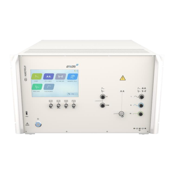
Figure 6-1 Axos Front view Pos. Function Description On/off switch Turns on and off the power of AXOS Surge impulse voltage monitor 1000:1 divider for surge impulse. Direct connection to output oscilloscope. Example: 5000Vsurge impulse outputs 5V on the BNC socket Surge impulse current monitor 1000A/V surge impulse current monitor. -
Page 28: Device Back Pannel
Save report data or test files onto USB memory stick Colour touch screen Every command and adjustment will be controlled and entered via the touch screen 6.2 Device back pannel Figure 6-2 Axos back pannel Pos. Function Description L “EUT Supply Input” (direct direct single-phase connection of power supply to the EUT. -
Page 29: Auxiliary Inputs And Outputs
HV DC Output Connection for TW8 module, up to 7kV DC output “Link” to external HAEFELY Input for HAEFELY transformer DIP 116 for voltage dips, then transformer DIP 116 adjustable on 0%,40%, 70% and 80% in reference to the U1 nominal voltage of AXOS8. - Page 30 Trigger output When Burst, Surge or Voltage dips package in use, signal becomes 0, after the applied package has finished the signal becomes 1(negation); used for indication of signal on oscilloscope Spare (Reserve) Not in use Operating Instructions...
-
Page 31: Setup Menu
Remote GUI Remote GUI is possible to access when license key purchased from the HAEFELY; switch on/off of communication between remote computer and AXOS8 possible Entering of new “coil Antenna” factor as described in capture 7.2.1... -
Page 32: Predefined Standard Program
Touch calibration In normal delivery mode there is a pre-calibration of the touch screen. However, if required, please follow and press for few seconds with a pen the cross at the screen. It requires five different positions. Then confirming and as a control measure four different yellow dots get open. Again confirming and the calibration has finished. -
Page 33: Defined Axos Commands
6.3.2 Defined AXOS Commands Predefined commands are available for the AXOS. Those commands will be given to the unit via LAN network. No Remote software is necessary. For example, remote control programs can be written in C language. -
Page 34: Icon Bar
CW:SET:TRANS_PHASE? CW:SET:TRANS_POL OFF CW:SET:TRANS_POL? This commands will be send to AXOS and test can be performed in accordance to it. 6.3.3 Icon bar The Table presents a overview of icons in the operating menu. The icons get displayed in the right upper corner of the operating menu, except position 3. -
Page 35: Surge
PrgItem_Res.csv : Test overview data However, with reporting software (capture 14.2) an automatic report gets created and can be used as a reference document for the executed test for instance. For further information contact your representative or HAFEELY directly. 7 Surge 7.1 General information Please read carefully the Table 5-1 and Table 5-2 in detail before first use of the Surge generator. -
Page 36: Open Circuit Voltage (Ocv)
7.2.1 Open Circuit Voltage (OCV) Figure 7-1 Open circuit voltage (OCV) [1] Front time: T1 = 1,67 x T = 1,2µs ± 30% Time to half value: T2 = 50µs ± 20% Verification of the Surge output signal (HI and COM) in the front view can be done with the help of the in capture 15.2.1 described PDP 8000. -
Page 37: Surge Menu
Test requirements must be achieved by the user according to the IEC 61000-4-5 norm. The safety standards as written in Table 1-1 must be unconditionally fulfilled, when operating the AXOS In the next step, the user selects either the pre-compliance or the standard operation mode. The Figure 7-3: Surge Standard mode and Figure 7-4: Surge pre-compliance mode reflects either of the appliance modes. - Page 38 For instance, in the Standard Mode after selecting the peak voltage field, the numeric display appears as shown in Figure 6-5. In a similar way works the repetition rate and the number of surge. Awareness is to give for line synchronization; hence, it has been described more detailed in the capture 6.3.4.
-
Page 39: Properties
Acoustic signal when test ends 7.2.5 Transition The Figure 7-8: SURGE transition mode reflects the transition window of the AXOS . The “alternative polarity” makes possible to switch between positive and negative impulses. Alternate polarity, peak voltage and phase can be selected and parameter entered. It is only possible to select phase in either external synchronization or synchronization mode. -
Page 40: Trigger
“peak voltage” sets the user through the touch screen in the main operating window. In “external trigger” the signal for the trigger comes from an external source and gets connected via PIN 11 in the AUX input at the rear view of the AXOS 7.2.7... -
Page 41: Magnetic Field
For the magnetic field the coil gets connected directly via banana plug to the surge output HI and COM as written in position 6 and Position 7 in Figure 6-1 Axos Front view. Only these outputs can be used for the Surge impulse. -
Page 42: Coil Antenna
Figure 8-2: Magnetic field Standard mode When “Line” button pushed, “EUT Supply Input” connected with L, N, PE front view and in the right corner the plug flashes red. After pushing the “Start” button the surge impulse gets applied. In Figure 8-3: Magnetic field charging is the Surge impulse proceeding. The magnetic field will be displayed and the safety symbol is flashing. -
Page 43: Transition
Figure 8-4: Coil Antenna factor from Set Up menu of AXOS8 To add a different coil, it will be entered in setup (Figure 6-3 Setup Menu). This selection can be seen in the operating menu in the magnetic field. 8.2.2 Transition In “Transition”... - Page 44 Line Current Limits the current (L, N, PE front view) to the EUT. Due to EUT fails, AXOS causes an action Action: Ignore, Alarm, Test stop, Test stop & line off which can be: Ignore, Alarm, Test Stop, Test Stop & Line off.
-
Page 45: Ring Wave (Axos Only)
CDN the polarity becomes important. It can be select either between the Hi and COM output or the coupling network (Position 9,10,11 in Figure 6-1 Axos Front view). Furthermore, 3 phase CDN, likely the FP SURGE100M2 or FP-COMB 32 can be chosen. -
Page 46: Ring Wave Menu
Test requirements must be achieved by the user according to the IEC 61000-4-12 norm. The safety standards as written in Table 1-1 must be unconditionally fulfilled, when operating the AXOS In the next step, the user selects either the pre-compliance or the standard operation mode. The Figure 9-2: Ring Wave Standard mode and Figure 9-3: Ring Wave pre-compliance mode reflects either of the appliance modes. -
Page 47: Properties
In Pre-Compliance Mode, the parameter values can be changed in set increments with the use of arrow keys or by pressing the number between the arrow keys. Pressing the number between the arrow keys will bring up the numeric display shown in Figure 9-4: Ring Wave peak voltage. Figure 9-4: Ring Wave peak voltage After values entered, the start button can be pushed and the window Figure 9-3: Ring Wave pre- compliance mode opens up, if selected pre-compliance mode. -
Page 48: Transition
Acoustic signal when test ends 9.1.4 Transition The Figure 9-7: Ring Wave transition mode reflects the transition window of the AXOS . The “alternative polarity” makes possible to switch between positive and negative impulses. Alternate polarity, peak voltage and phase can be selected and parameter entered. It is only possible to select phase in either external synchronization or synchronization mode. -
Page 49: Trigger
“peak voltage” sets the user through the touch screen in the main operating window. In “external trigger” the signal for the trigger comes from an external source and gets connected via PIN 11 in the AUX input at the rear view of the AXOS 9.1.6... - Page 50 (according to ANSI standard) is indicated in Figure 9-8: ANSI Output & Coupling Paths Ring Wave. Figure 9-8: ANSI Output & Coupling Paths Ring Wave Figure 9-9: Figure 8-8 IEC Output & Coupling Paths Ring Wave (Axos8 Only)
-
Page 51: Telecom Wave (Axos Only)
Telecom Wave (Axos only) 10.1 General Information This impulse is characterised as a telecom wave impulse as well as 10/700 impulse. The reason is that under OCV condition the front time is defined with 10µs and time to half value is 700 µs. -
Page 52: Short Circuit Current (Scc) Telecom Wave
10.1.2 Short Circuit Current (SCC) Telecom Wave Figure 10-2: Short Circuit Current (SCC) Telecom Wave Front time: = 1,25 x T = 5 µs ± 20% Time to half value: = 320 µs ± 20% 10.1.3 TW 8 module When external TW 8 (Figure 10-3: Telecom Wave module) module is connected it gets automatically indicated via the link cable (intelligent input). -
Page 53: Axos 8 + Tw 8
Test requirements must be achieved according to the IEC 61000-4-5 ed.3 norm. The safety standards as written in Table 1-1 must be unconditionally fulfilled, when operating the AXOS The high voltage signal gets applied directly from HV DC output of the AXOS8 to the HV DC input of the TW 8 module in the rear side of the unit. - Page 54 Figure 10-5: Telecom Standard mode When pressing the “home” button the user gets transferred automatically to the start menu. In the Figure 10-6: Telecom Wave pre-compliance mode it shows the use of the pre-compliance mode. Indeed, every parameter can be changed by simply pressing on the black bows next to the value.
-
Page 55: Output & Coupling Paths
10.1.5 Output & Coupling Paths In the figure below there are three different (1 x 15 Ohm, 4 x 40 Ohm, 4 x 40 Ohm gas arresters) output options in accordance to IEC 61000-4-5 ed.3 standard. It can be simply connected vie banana plugs with the EUT. -
Page 56: Transition
10.1.7 Transition . The “alternative polarity” makes The Figure 9-10 reflects the transition window of the AXOS possible to switch between positive and negative impulses. Alternate polarity, peak voltage can be selected and parameter entered. Figure 10-10: Telecom Wave transition mode After successfully entering the parameter, “OK”... -
Page 57: Electrical Fast Transient Burst
Electrical Fast Transient Burst 11.1 General information The Burst generator generates Electrical Fast Transient Bursts (EFT) as described in IEC 61000- 4-4. The source impedance of the generator is 50 Ω. The burst is a common mode transient, coupled simultaneously to all selected paths with respect to ground. It can be selected between using the coaxial output or the built in mains coupling network. - Page 58 Figure 11-1: EFT/BURST Standard mode By pressing at each particular value, a new parameter (Figure 11-1: EFT/BURST Standard mode) can be entered. Then confirming with “OK” and the parameter will be written in the standard test mode. In Addition it can be immediately selected between kV and V. Figure 11-2: EFT/BURST peak voltage configuration The following graphic represents the pre-compliance mode.
-
Page 59: Output & Coupling Paths
In Burst testing mode every line signal gets tested against GND (PE). In direct output the signals stands on the position 8 in Figure 6-1 Axos Front view. It gets connected directly to the EUT or will be used for verification of the Burst waveform. Furthermore, it can be connected to three- phase test CDN. -
Page 60: Transition
Alarm, Test Stop or test stop & line off) Line Current Limits the current (L, N, PE front view) to the EUT Due to EUT fails, AXOS cause an action which can Action: Ignore, Alarm, Test stop, Test stop & line off be: Ignore, Alarm, Test Stop, Test Stop &... -
Page 61: Synchronization
0°to 359°. However, if no power supply is connected to the EUT supply input at the rear view, it has to be entered “Async.”, otherwise it is impossible to get a Burst waveform in the output. In external synchronization, the output with the position 8 Figure 6-2 Axos back pannel in the rear view is in use. -
Page 62: Voltage Dips & Interrupts
Voltage dips & interrupts 12.1 General information For the voltage dips & interrupts only the EUT will be connected via the line outputs (L, N, PE) in the front view. The EUT Supply Input (L, N, PE) in the rear view gets connected to the power supply. -
Page 63: Dips
To create the Voltage dips an external transformer is necessary, because a second voltage level is required. When purchasing the DIP 116 from the HAEFELY AG the position 5 at the rear view graphic can be used. The Figure 12-2: DIP 116 Transformer connected gets displayed when DIP 116 is successfully connected. -
Page 64: Transformer Dip 116
12.3.1 Transformer DIP 116 The HAEFELY AG DIP 116 transformer will be connected through the V Dip and the Link input at the rear view of the AXOS . The DIP 116 has an independent connection to an external power supply via banana plug. -
Page 65: External Transformer
Then V dip 0%, 40%, 70% and 80% in reference to U1 nominal. Only with the DIP 116 the proportional voltage adjustment through the menu is possible. The second main advantage will be reflected in the compatibility of the transformer with the AXOS compact immunity tester. -
Page 66: Properties
Alarm, Test Stop or test stop & line off) Line Current Limits the current (L, N, PE front view) to the EUT. Due to EUT fails, AXOS cause an action Action: Ignore, Alarm, Test stop, Test stop & which can be: Ignore, Alarm, Test Stop, Test line off Stop &... -
Page 67: Trigger
Figure 12-7: Voltage Dips Transition When finalizing the parameter, it must be confirmed with “OK” and either the pre-compliance or standard mode gets open depending what selection was previously done. In addition the incremental intervals get displayed at each particular function name, like for example “interval”. 12.3.5 Trigger The trigger can be accessed either from pre-compliance mode or standard mode when generator... -
Page 68: Sequence
Sequence menu To access the sequence menu the “sequence” button must be selected in the starting screen of the AXOS Figure 13-1: Sequence In the left corner of the Figure 13-1: Sequence you can select between adding a new impulse, moving the step back and forward or simply deleting the entire function. - Page 69 Figure 13-2 Properties Sequence The “EUT fail Action” is linked to the menu of the properties setting in the particular impulse menu. There it can be for example the SURGE menu (when SURGE selected, could be also Ring Wave, Telecom Wave, or any other impulse). The next graphic displays the SURGE properties menu.
-
Page 70: Add Step In Sequence
Figure 13-4 Content in description menu of Sequence As a conclusion those information can be printed in the reporting tool of AXOS . An example of the layout, header and content is shown below. (“reporting software”) Figure 13-5 Test Report 13.2.1... - Page 71 When loading an existing “file” (which had been previously saved on internal SD card), “load” button must be selected. It works similar as in operating menu of single impulse form, for example combination wave generator. Important: No new test can be created, only existing file can be loaded from either the internal or standard directory.
-
Page 72: Start Sequence
Selected Steps can be moved up, down or can be deleted by buttons At bottom of Sequence Steps main parameters of selected Step are shown. 13.2.2 Start Sequence After selecting the start following three options get displayed: When selecting all steps every command gets applied to EUT and after finished following windows gets shown in accordance to programmed function. -
Page 73: Manually Set & Complete Sequence Result
(Passed or Failed). EUT immunity pass/fail criteria can be selected in Figure 12-9 as well. Figure 13-9: Figure 12-9 Sequence result Criteria is saves when returining to sequence or after Axos is turned off. 13.2.4 Clearing of result Sequence button for clearing the test results column. -
Page 74: Reporting Of Data
If you edit a Test Step, result will be cleared. Figure 13-11: Sequence Test result of step cleared Results will be cleared if you edit a test step. 13.3 Reporting of data Report data is saved automatically or manually by REPORT button, according AXOS Setup Report Data Saving Sequence... - Page 75 Each save of Report Data will create a folder on AXOS internal storage and if insert, on external USB stick. This is same as for single Test Report. Floppy symbol in header of Sequence dialog is blinking while report data saving to internal storage or external USB stick, and also while saving.
-
Page 76: Remote Software
“remote GUI” section becomes enabled in Figure 5-3. When operating via WLAN only one remote device can control the AXOS , because of safety measures. However, it can be controlled parallel via remote device and touch screen of AXOS 14.1.1 “Point to point” remote control Connect Ethernet cable to RJ45 input at the rear view and to remote device, e.g. - Page 77 Enter the new IP address as showed in the AXOS operation window (e.g. Figure 14-2: Ethernet communication), however, the last digit must have ± 2 difference to initial IP address of AXOS Confirm with ok. In the last step starting of installed free software “VNC Viewer”. Entering of exact IP-Address as displayed in Figure 14-4 as seen in the AXOS operating window (e.g.192.168.1.100).
-
Page 78: Wlan" Remote Control
“point to point” connection must be followed. However, when the network selection happens automatically, the DHCP must be ticked as below. Press “renew” and the IP Address will be given automatically to the AXOS Figure 14-5: Communication, MAC Address In the next step the automatic given IP address can be written in the VNC Viewer. -
Page 79: Reporting Software
14.2 Reporting Software The reporting software creates automatically a test report. (Figure 12-5) The main header can be adjusted with for example individual logo of calibration laboratory or individual company. The input of data can be either supplied directly via the remote control software or when saving the data on a USB device. -
Page 80: Troubleshooting
Measurement data and / or print screen will be of tremendous help for locating and solving problems. 15.2 Error Messages In the menu is a short summary of possible alarm messages which can occur when operating the AXOS 15.2.1 Troubleshooting Alarm message Possible cause... - Page 81 I EUT requires more than 16 A support nominal required current, may EUT defect, short circuit EUT, protection of AXOS EUT requires more than 16 A support current, may EUT defect, short circuit EUT requires more than 16 A support...
-
Page 82: Logic Errors
AXOS for repair at system startup internal supply voltage 24V is out of range - bad or missing Function Key - go to Setup License - internal storage card missing or damaged Manager and check for correct numbers - send for repair... - Page 83 Incompatible settings Increase burst period, repetition Frequency Decrease Burst duration, Rep. Too many spikes per packet Frequency, Increase Burst period Incompatible settings for pre-compliance Burst mode must be set to Normal, Trigger must be set to mode Auto, Transition must be set Decrease peak voltage,...
-
Page 84: Service, Maintenance And Contact Information
Service, Maintenance and Contact Information HAEFELY has a worldwide network of representatives and local service points providing a wide range of services way beyond standard customer support for sales and after-sales inquiries. Highly skilled and experienced customer support teams guarantee you seamless worldwide service for all our products. -
Page 85: Maintenance
16.3 Verification In the next captures are descriptions of our additional verification equipment for the AXOS . If further information required of any of the equipment, please either contact your sales representatives or the HAEFELY AG technical support team directly. -
Page 86: Waveform Scc (Surge)
16.3.3 Electrical fast transient/Burst The HAEFELY EFT Verification Kit includes a 50 Ω and 1000 Ω attenuator as required in the IEC 61000-4-4 standard. The appropriate attenuator is fitted to the “Burst” coaxial output, and an oscilloscope is then connected to the output of the attenuator. For measuring the waveform at the output of the coupling filter, single phase and three phase adapters are available. -
Page 87: Burst Verification Adapter
Additionally, an EFT verification adapter is available for testing of every single phase (L, N, PE front view from AXOS). It gets connected with the PE pin (Pos. 12 Figure 5-1) and every single phase (L, N, PE Figure 5-1).The BNC output of the burst adapter is then connected to the oscilloscope. -
Page 88: Calibration
16.4 Calibration Calibration period of the AXOS has to be determined by the user, and depends on the intensity of use and end user requirements. However, it is recommended every 2 years. The AXOS is factory calibrated before shipped and supplied with the calibration certificate in accordance to ISO 9001 management standard. -
Page 89: Support
16.7 Support Software Updates HAEFELY runs an Internet Update webpage where owners of our test instruments can download the latest firmware, software, manuals, related information etc. The HAEFELY update page can be reached after log in: http://www.haefely.com/ Technical Support If persistent problems or faulty operation should occur, please contact the Customer Support Department of HAEFELY or your local agent. -
Page 90: Addresses / Webpage
+41 61 373 4444 Service Phone emc-support@haefely.com Service E-Mail 16.8.2 China Office Haefely AG Representative Beijing Office 8-1-602, Fortune Street | 67, Chaoyang Road, Chaoyang District | Beijing, China 100025 + 86 10 8578 8099 Phone + 86 10 8578 9908 sales@haefely.com.cn Sales E-Mail 16.8.3... -
Page 91: Transport And Storage
Transport and Storage 17.1 Transport and Packaging The packing of the equipment provides satisfactory protection for normal transport conditions. Nevertheless, care should be taken when transporting the equipment. If return of the equipment is necessary, and the original packing crate is no longer available, then packing of an equivalent standard or better should be used. -
Page 92: Disposal, Recycling And Onward Transfers
Disposal, Recycling and Onward Transfers When the equipment reaches the end of its working life it can, if required, be disassembled and recycled. No special instructions are necessary for dismantling. The instrument is constructed of metal parts (mostly aluminium) and synthetic materials. It might contain batteries (see the product specification). - Page 93 Conformity Conformity...
- Page 94 Notes Notes...
- Page 96 + 86 10 8578 8099 sales@haefely.com sales@haefely.com.cn This document has been drawn up with the utmost care. We cannot, however, guarantee that it is entirely complete, correct or up to © date. Copyright HAEFELY/ Subject to change without notice...
Need help?
Do you have a question about the AXOS and is the answer not in the manual?
Questions and answers