Table of Contents
Advertisement
Quick Links
Advertisement
Table of Contents

Related Manuals for Weller WA2000

Summary of Contents for Weller WA2000
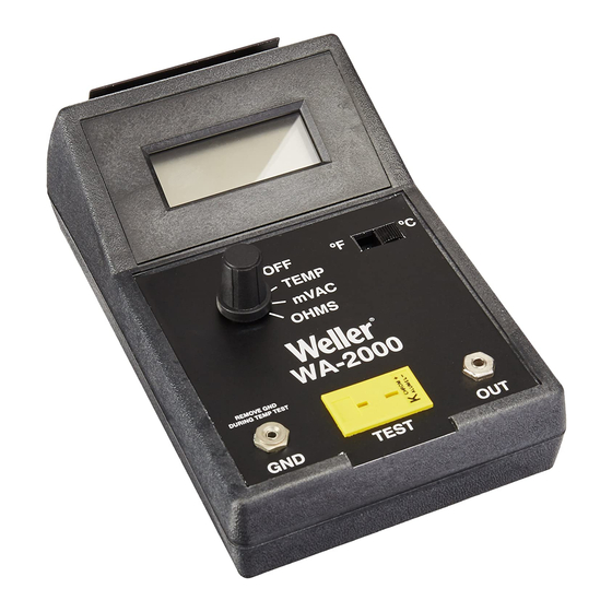
- Page 1 WA2000 SOLDERING IRON ANAL YZER INSTRUCTION MANUAL...
- Page 2 INTRODUCTION The WA2000 soldering iron analyzer was developed for testing soldering irons for compliance with the DOD-STD-2000 and the new MIL-STD-2000 specifications. This portable unit is capable of testing tip temperature, tip to ground resistance and tip to ground noise (mVRMS). Correctly used and maintained, it is the most accurate of any comparable tester currently available on the market.
-
Page 3: Temperature Stability
If using a pyrometer, place the tinned tip of the iron to be tested onto the contact pyrometer. Using the iron "holder" provided with the WA2000 will aid in obtaining an accurate reading. Add additional solder to increase contact area to each side of the pyrometer. - Page 4 TIP TO GROUND RESISTANCE The WA2000 is capable of measuring tip to ground resistance up to 100.0 ohms. Per the MIL-STD-2000 specification, an iron's tip to ground resistance must not exceed two ohms.
-
Page 5: Recorder Output
MEASUREMENT PROCEDURE Set the analyzer rotary selector switch to the OHMS position. Insert the yellow plug from the ground adapter into the analyzer TEST receptacle and the ground pin into the GND receptacle. Record lead resistance R , which will be subtracted later. Remove yellow plug from the analyzer TEST receptacle and reinstall pyrometer. - Page 6 MIL SPECIFICATION REQUIREMENTS AND FREQUENCY OF PERIODIC TESTS REQUIREMENT MIL-STD-2000 DOD-STD-2000 WS-6536 Tip to ground, max. 2.0 ohms quarterly 2.0 ohms quarterly 20.0 ohms daily resistance, hot Tip to ground, max. 2.0 mv biannually 2.0 mv biannually 2.0 mv monthly voltage, hot Tip temperature, at ±10°F monthly...
-
Page 7: Display Calibration
CONTACT PYROMETER MAINTENANCE The contact pyrometers have been designed for accuracy, ease of use and low cost. As with any pyrometer, certain guidelines should be followed in order to obtain maximum precision of measurement. Prior to use, it is important that the wire ends (A) be inspected and cleaned if necessary. -
Page 8: Ohms Calibration
mVAC RMS CALIBRATION Set the analyzer rotary selector switch to mVAC. Connect a signal generator to the analyzer TEST and GND receptacles. The test cable should include an internal two ohm load from input (TEST) to ground (GND). With no signal applied (zero signal), adjust R80 for a reading of 00.0 on display. Allow time for the reading to settle, it will take several seconds. -
Page 9: Customer Service
CUSTOMER SERVICE Should your WA2000 analyzer require repair, it may be sent to the following address: CANADA COOPERTOOLS- WELLER DIVISION COOPERTOOLS 1000 Lufkin Road 164 Innisfil Street Apex, NC 27539 Barrie, Ontario, Canada L4N3E7 Attn: Repair Dept. Attn: Repairs Phone: 1-800-476-3030 Phone: 1-705-728-5564 Ext.
Need help?
Do you have a question about the WA2000 and is the answer not in the manual?
Questions and answers