
Subscribe to Our Youtube Channel
Related Manuals for Toledo Brake Monitor

Summary of Contents for Toledo Brake Monitor
- Page 1 Brake Monitor Toledo Integrated Systems Toledo Transducers, Inc. Installation and Operation Manual...
- Page 2 Doc #0017289 Brake Monitor Operator Manual...
- Page 3 Brake Monitor Operator Manual Revision: 3.0 Doc #0017289 Brake Monitor Operator Manual...
- Page 4 The software and sensors are warranted by the manufacturer, Toledo Integrated Systems, to be free from defects in workmanship for one year from the date of the manufacturer’s shipment. This warranty is limited to the functions of the Brake Monitor as stated in this manual.
-
Page 5: Table Of Contents
TABLE OF CONTENTS SECTION 1 Brake Monitor OPERATION KEYS..........4 1.1 Adjusting the Contrast ................4 1.2 Display Back Light.................4 1.3 Home Key ....................5 1.4 Back Key ....................5 1.5 Reset Key ....................5 1.6 Up and Down Arrow Keys ..............5 1.7 Enter Key....................5 1.8 Alpha-Numeric Keys... - Page 6 TABLE OF CONTENTS APPENDIX A DRAWINGS BRAKE MONITOR TERMINAL STRIP LAYOUT ..........I ENCODER CABLE WIRING................II ENCODER DIMENSIONS..................III BRAKE MONITOR MOUNTING DIMENSIONS..........IV Doc #0017289 Brake Monitor Operator Manual Page 3...
-
Page 7: Section 1 Brake Monitor Operation Keys
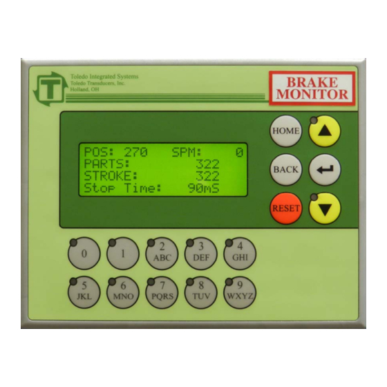
SECTION 1 Brake Monitor Operation Keys The Brake Monitor comes standard with parts and stroke counters and immediate stop output. The above picture shows the operation keys that will be used throughout the manual. 1.1 ADJUSTING THE CONTRAST If the screen is either too dark or too light, the contrast can be adjusted by pressing and holding the <ENTER>... -
Page 8: Home Key
1.7 ENTER KEY The <ENTER> Key is used to submit information to the Brake Monitor. 1.8 ALPHA-NUMERIC KEYS The Alpha-numeric Keys are used when making selections from the displayed options. -
Page 9: Section 2 Home Screen
For an explanation of how to reset the Stroke Counter, refer to Section 2.5 Back Key – Reset Counters. 2.4 STATUS MESSAGE The Status Message display line will show the last Stop Time, if no faults are present. If a fault is present it will display the fault. Doc #0017289 Brake Monitor Operator Manual Page 6... -
Page 10: Back Key - Reset Counters
Stroke Counter Value. To move the cursor to the Parts Counter, press the <ENTER> key. When all settings on this page are acceptable, press the <BACK> key to return to the Home screen. Doc #0017289 Brake Monitor Operator Manual Page 7... -
Page 11: Section 3 Menu Select Screen
From the Menu Select Screen, you can maneuver to the different settings within the Brake Monitor. The following four functions can be accessed from this screen: View Brake Monitor, Edit Brake Monitor, 90 DEG BRAKE TEST and System Setup. To protect the system settings, a password is required for all functions except View Brake Monitor. -
Page 12: Section 4 View Brake Monitor
To view the current Brake Monitor settings, access the Menu Select Screen, select View Brake Monitor and press the <ENTER> key. You will be taken to the following screen. This screen shows the last Stop Time, and the Allowable Stop Time. Press the <BACK>... -
Page 13: Section 5 Edit Brake Monitor
SECTION 5 EDIT BRAKE MONITOR If it is necessary to modify any of the Brake Monitor settings, access the Menu Select Screen, select Edit Brake Monitor and press the <ENTER> key. The following screen will appear. Type the password using the alpha-numeric keys, then press the <ENTER> key. If the wrong password is entered, the screen will flash “INCORRECT PASSWORD”. - Page 14 SECTION 5 EDIT BRAKE MONITOR After entering the correct password, you will see the Edit Brake Monitor screen (shown below). The Allowable Stop Time value will be blinking. Enter a new value by using the alpha-numeric keys. The valid range for Allowable Stop Time is 0-1000 milliseconds (i.e.
-
Page 15: Section 6 90 Deg Brake Test
90 degrees. The bottom line of the display indicates the stopping time from the last time the test was performed. Brake tests should be performed periodically to check the condition of the brake. Doc #0017289 Brake Monitor Operator Manual Page 12... - Page 16 8) Once the press comes to a complete stop, the bottom line will display the stopping time. 9) Brake test is complete. To cancel a 90 Degree Brake Test, press the <BACK> key at any time during the process. Doc #0017289 Brake Monitor Operator Manual Page 13...
-
Page 17: Section 7 System Setup
Restore Defaults, Edit Passwords and No Motion. Use either the alpha-numeric keys or the arrow keys to select which System Setup to edit. When the correct selection is flashing, press the <ENTER> key. Doc #0017289 Brake Monitor Operator Manual Page 14... -
Page 18: Set Press Angle
(0-359). The offset can be calculated by determining the number of degrees the displayed angle is from the actual angle of the press. 5) When the correct offset is displayed, press the <ENTER> key. Doc #0017289 Brake Monitor Operator Manual Page 15... -
Page 19: Restore Defaults
Control will return to the System Setup Menu. To quit before restoring the factory defaults, press the <BACK> key. Control will return to the System Setup Menu. Factory Defaults: Allowable Start Time = 500mS Allowable Stop Time = 500mS Doc #0017289 Brake Monitor Operator Manual Page 16... -
Page 20: Edit Passwords
1) Setup – This level gives the user access to all functions except for Edit Brake Monitor and System Setup. 2) Global – This level gives the user access to all functions of the Brake Monitor. The unit comes factory set with the passwords disabled (set to 0). Make sure to change these passwords to protect the data from accidental changes. -
Page 21: No Motion
If the Start Time (the time it takes from when the power to the clutch valve is applied, until the ram starts moving) is longer than the Allowable Start Time, an alarm will occur. Doc #0017289 Brake Monitor Operator Manual Page 18... -
Page 22: Faults
8.3 BRAKE MONITOR FAULT This fault occurs when the stopping time of the press exceeds the Allowable Stopping Time. Refer to Section 5 Edit Brake Monitor for an explanation on setting the Allowable Stop Time. Doc #0017289 Brake Monitor Operator Manual... -
Page 23: User Notes
USER NOTES Doc #0017289 Brake Monitor Operator Manual Page 20... - Page 24 USER NOTES Doc #0017289 Brake Monitor Operator Manual Page 21...
-
Page 25: Revision History
REVISION HISTORY 4/2013 REV 3.0 Initial Release Doc #0017289 Brake Monitor Operator Manual Page 22...
Need help?
Do you have a question about the Brake Monitor and is the answer not in the manual?
Questions and answers