
Related Manuals for Morgana AutoCreaser Pro 33A


Summary of Contents for Morgana AutoCreaser Pro 33A
- Page 1 70-209 Issue D April 2021 AutoCreaser Pro 33A (CB/UL) SERVICE MANUAL Document Creasing Machine Morgana Systems Limited United Kingdom www.morgana.co.uk Telephone: ( 01908 ) 608888 Facsimile: ( 01908 ) 692399...
- Page 2 ... Introduction The purpose of this manual is to explain the procedure for dis - mantling and re-assembly of the major assemblies on the Morgana Auto Creasing machine. All the engineering adjustments are shown at the end of each relevant section.
- Page 3 AutoCreaser Pro 33A INTRODUCTION Pan head and Cross - head countersunk screws all have metric Taptite threads and Pozi - drive recesses. Use No.2 point Pozidriv or Supadriv drivers for all screws M4 & above, and No.1 point drivers for M3 & below.
- Page 4 INDEX Introduction …………………………………………………………………………. Introduction Fasteners Identification New Machine Preparation Section 1 …… Covers………….….………………………………………………. Section 2 …….Vacuum Drum ……………………………………………………. Suction Drum and Belt Removal/Replacement Section 3 ……Removal of Butterfly Valve Assembly........Removal of Unit Section 4 ……Main Creaser Mechanism ............Removal of Unit Section 5 …….Removal /Replacement Stepper Drive Belt / Pulleys …………...
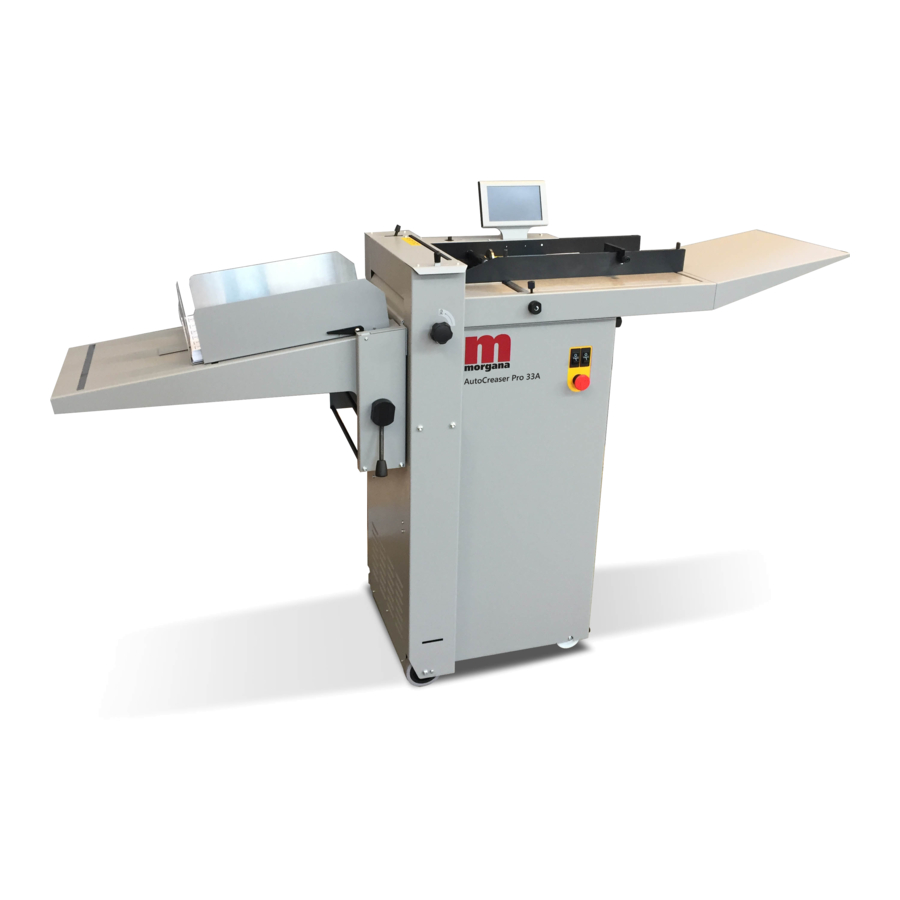
- Page 5 AutoCreaser Pro 33A AutoCreaser Pro 33A DOCUMENT CREASING MACHINE Key to photograph below SYSTEM Page 5...
- Page 6 SECTION 1 1.1 The Front Cover The front cover which is situated below the feed bed also covers the compressor and is secured by 13 taptite screws and is located by three tongues protruding into the main frame. To remove this cover, remove all screws and twist forwards to clear emergency stop button and mains socket, pull out to release the tongues.
- Page 7 AutoCreaser Pro 33A SECTION 2 VACUUM DRUM REMOVAL / REPLACEMENT. 1. Remove the Compressor cover below the feed bed. 2. Remove the top stainless steel feed bed. 3. Remove the moving side guide. 4. From the underside of the fed table loosen the valve assembly by unscrewing the two M5 posi pan head screws, allow the assembly to hang on its two pipes.
- Page 8 VACUUM DRUM FEED BELT REMOVAL / REPLACEMENT. Drum Drive Belt replacement. 1. Following stages 1 to 6 above, the belt can be removed from the vacuum drum. 2. Remove the slot sensor from the motor mounting bracket. 3. The belt can now be removed from the machine. Replacement is the reverse procedure.
- Page 9 AutoCreaser Pro 33A BLANK PAGE SYSTEM Page 9...
- Page 10 SECTION 3 Removal of Butterfly Valve Assembly. The Butterfly Valve assembly is located on the underside of the feed bed, towards the back of the machine. 3.1 Remove the two pipe mounting clip plates (ITEM 5 on page 11) so that the hoses can be detached from the valve.
- Page 11 AutoCreaser Pro 33A SYSTEM Page 11...
- Page 12 BLANK PAGE Page 12 CREASING...
- Page 13 AutoCreaser Pro 33A SECTION 4 MAIN CREASER MECHANISM REMOVAL OF UNIT First access should be gained by removing the top infeed and outfeed guards (See Section 1) Detach guard micro switch by removing two screws, taking care not to drop them.
- Page 14 Place the unit on a solid and clear bench ensuring no wires are trapped beneath the metal side plates. Assemble loosely the green drive belt to the pulley 4.10 Replace the unit ensuring the wiring harness is threaded as it was removed 4.11 Attach the belt to the drive shaft.
- Page 15 AutoCreaser Pro 33A SECTION 5 REMOVAL/REPLACEMENT STEPPER DRIVE BELT/ PULLEYS Loosen the adjuster nut from the inside unit and slide the belt off. Loosen the securing socket set screws in the drive pulley on the roller for it to be removed (NOTE there is one screw located in a hole in the shaft) Refitting the belt is a reverse procedure.
- Page 16 SECTION 6 REMOVAL/REPLACEMENT OF TOP INFEED ROLLLER With the unit on a bench Remove the drive belt and flanged pulley from the bottom infeed roller. Viewing on the outside of the sideplate, align the lug on the eccentric with cutout in the sideplate. Using a soft mallet gently tap the roller assembly from the opposite side supporting its length as it emerges.
- Page 17 AutoCreaser Pro 33A SECTION 7 DRIVE HUB: REPLACE RUBBER TORSION BUSH (SHOCK ABSORBER). 7.1 Loosen grub screws in one half of hub. Slide hub outward & remove rubber torsion bush. Replace in reverse order. Rubber Torsion Bush SYSTEM Page 17...
- Page 18 SECTION 8 Blade Home Micro Switch Replacement 8.1 Remove 464-01-030 M3 Nyloc Nut and 481-030 M3 Washer Plain. 8.2 Carefully remove 76-379-01 Adjuster with 613-191 Micro Switch attached & 76-086- 03 Shouldered Pad. 8.3 Separate 613-191 Micro Switch from 76-379-01 Adjuster by releasing 403-01-030- 020 M3x20Lg Cap Head, 481-030 x2 M3 Washer Plain &...
- Page 19 AutoCreaser Pro 33A SECTION 8 Blade Home Micro Switch Setting 8.6 Rotate the camshaft in the direction shown in Fig.8.1 so that the slot detector (flag) 76-377-01 moves out of the sensor 76-156. 8.7 Adjust the micro switch position by turning the nyloc nut 484-01-040 so that the sensor activates (clicks) when the edge of the sensor flag is 7-8mm from the sensor as in picture Fig 8.2.
- Page 20 SECTION 9 ELECTRICS: The PRO Control System. The Morgana PRO control system is essentially a computer system just like the PC you use at home. Unlike your Microsoft Windows PC, the PRO system uses a LINUX operating system and runs only one program, which is the machine control program for the particular machine that it is installed on.
- Page 21 AutoCreaser Pro 33A SECTION 9 ELECTRICS: REMOVAL/REFITTING PCB/POWER SUPPLY ASSEMBLY All the Electric controls and pcbs are located within the rear cover mounted on a common base plate. REPLACEMENT OF MAIN CONTROL P.C.B. This PCB controls all functions of the machine and houses the Main Program PCB.
- Page 22 SECTION 9 REPLACEMENT OF PIC PROCESSOR BOARD. (see Tb2822) This Small PCB is plugged onto the face of the Main Control PCB and houses the Program Chip. The use of an antistatic wrist band should be used during work on this PIC Processor PCB. Switch the mains power off and disconnect from the mains supply.
-
Page 23: Installation Procedure
AutoCreaser Pro 33A SECTION 9 Installation Procedure. 1. Note the current machine calibration settings. 2. Power down the machine and remove the power cord. 3. Replace the USB Flash Drive. 4. Power the machine up. 5. To access the machine menu, open the calculator and type 608888; then press X to exit the calculator screen. - Page 24 SECTION 9 Lock Recess USB Flash Drive FIG.1 Lock Recess FIG.1 above shows the USB Module plugged into the USB port on the Gigabyte ITX motherboard type J3455N-D3H. Internal USB Flash Drive Jetway ATX Mother Board Jetway ATX Mother Board Asrock ATX Mother Board Asrock ATX Mother Board Page 24...
- Page 25 AutoCreaser Pro 33A SECTION 9 ITX BOARD REPLACEMENT. (see TB2822) The ITX mother board supplies the graphics to the touch screen display, to remove.- 1. Switch the mains power off. 2. Cut cable ties and unplug the all plugs. 3. Unscrew the four fixing screws attaching the board to the plate and remove from the machine.
-
Page 26: Replacing The Touch Screen Assembly
SECTION 9 Replacing the Touch Screen Assembly Replacing the Touch Screen Assembly. Ensure the mains power is turned off but with the plug in the socket, this maintains an earth to reduce static damage. 1. Remove the rear cover to expose the electrical panel. 2. - Page 27 AutoCreaser Pro 33A DIAGNOSTICS and CALIBRATION TOOLS. To enter the engineers tools menu. Turn the Machine on. Insert the Engineers Plug into the Socket located at the rear of the machine. Select Tools on the Display and continue to select required tool.
- Page 28 Page 28 CREASING...
-
Page 29: Controller Pcb
AutoCreaser Pro 33A PSU ASSEMBLY (76-272) DRIVE SIGNAL LEAD (75-436) BLADE SIGNAL LEAD (75-437) SYSTEM SWITCH COIL LEAD (75-364) STACKER GUARD SWITCH LEAD (75-232) HOME SWITCH LEAD (75-231) BLADE POSITION SENSOR LEAD (76-156) EDGE DETECT LEAD (76-230-03) DUAL SENSOR LEAD (76-154) -
Page 30: Cleaning The Sensors
SECTION 10 Optical Sensors - Cleaning and Setting Cleaning the Sensors With blades removed the optical sensors are accessible for cleaning on either side of the creaser unit - use a soft brush or cloth to remove any dust that may have collected onto the sensor lens. - Page 31 AutoCreaser Pro 33A SECTION 10 The Crunch Sensor uses a beam projected across the machine just in front of the blade and above the paper path, when the beam is broken the machine will stop. The receiver is housed in the Side Plate of the machine and is on the Operator Side, whilst the transmitter is housed in the Side Plate of the machine on the Lay Side.
-
Page 32: Section 11 Trouble Shooting
SECTION 11 Trouble Shooting Calibration of creasing position The length between the leading edge of the sheet and the 1 crease position can be calibrated in the event of the machine creasing out of position. Also the last crease closest to the back of the sheet can be adjusted relative to the 1st crease position this compensates for the inaccuracy of manufacture of the input roller Diameters. - Page 33 AutoCreaser Pro 33A Section 11 Trouble Shooting Fault Reason Solution Erratic register of Damaged roller surface Replace rubber rollers the Creaser Check Gap Setting Reset & tighten to ensure rollers are driving card. Faulty Drive motor Remove and replace motor assembly.
- Page 34 Section 11 Trouble Shooting Fault Reason Solution Edge & Crunch Sensors Check supply voltage Black lead of meter on tab IC8 (Main PCB) - Transmitters Should read 1.3Vdc Red lead of meter on red wire of CN8 and yellow wire of CN16 To Adjust these voltages Adjust VR4 Edge sensor &...
- Page 35 AutoCreaser Pro 33A FAULT:- ‘NO SYNC’ appears on touchscreen. (Machine will not boot up). 1. CHECK THE ATX POWER SUPPLY AS FOLLOWS:- (i) Disconnect the 20/24 way ATX power supply connector from the ITX Motherboard. (ii) Using a piece of tinned copper wire, short out the GREEN and BLACK wires of the connector as shown in FIG.1 below...
- Page 36 PINS 3 & 4 FIG.2 IMPORTANT RECYCLING NOTE:- The ITX mother board has a lithium battery fitted, the board together with its battery must be recycled in compliance with agreed national Procedures. Please contact your local disposal authority for information. CAUTION.
- Page 37 Check 500mA fuse, below the Mains Input connector (See Page 38). · IMPORTANT. If this fuse has blown replace it must be replaced with a T500mA fuse, Morgana part number 681-020. Is there a V DC output from the ATX PSU? (See page 34). Replace the ATX PSU.
- Page 38 FUSE YELLOW ORANGE T315mA Morgana Systems Ltd PUMP OVERLOAD BOARD WHITE WHITE If this fuse has blown it must be replaced with a T315mA fuse, Morgana part number 681-011. Page 38 CREASING...
- Page 39 AutoCreaser Pro 33A FUSE POSITIONS & RATINGS ANTI-STATIC UNIT TRANSFORMER ASSY. (IF FITTED) T5AH 250V (47061) T315mAH 250V (681-011) PSUs (24V & 48V) MAINS IN T4.0AH 250V (681-015) T15AH 250V (652-047) SYSTEM Page 39...
-
Page 40: Revision History
REVISION HISTORY Rev. Mod No. Mod Description Date Mod By ECO2923 Page 24 - Fig. 2 (microSD) removed. Fig. 1 Updated to show correct USB Module 14/06/19 ECO2968 Page 29 - Home switch setting procedure added. 05/12/19 Page 28 - T5AH Fuse was T500mA. ECO2997 23/04/21 Page 39 - T5AH Fuse was T500mA (681-020).
Need help?
Do you have a question about the AutoCreaser Pro 33A and is the answer not in the manual?
Questions and answers