
Related Manuals for MSI TI-600

Summary of Contents for MSI TI-600
- Page 1 ..20 Dixie Iron Works, Ltd. 300 W. Main St. Alice, TX 78332 www.diwmsi.com (800) 242-0059 (361) 664-6597 TI-600/QI-1000 Technical Manual for 600 HP Triplex/1000 HP Quintuplex MSI TI-600 Pump/ MSI QI-1000 Pump Revision 0 October 2019...
- Page 2 Table of Contents Location Title Section 1 General 1.00 General Description 1.10 Recommended Shipping & Storage 1.20 Drawings-Complete Pump Assembly 1.30 Drawings-Pump Assembly-Overall Dimensions 1.40 Drawing-Dual Pump Configuration-Overall Dimensions 1.50 Drawings-Gear Reducer Installation Positions 1.60 600 HP Pump Performance Data 1.70 1000 HP Pump Performance Data Section 2...
- Page 3 Section 4 Lubrication System 4.00 Drawing- Schematic on Lube System 4.10 Drawing- Power Frame Lube Lines-Dual Lube Pipe 4.20 Drawing- Gear Reducer Lube Lines 4.30 Recommended Lubrication Specifications 4.40 General Service Lube Oils for Power Frame 4.50 Cold Temperature Service Lube Oils for Power Frame 4.60 High Temperature Service Lube Oils for Power Frame 4.70...
- Page 4 6.40 Removing the Plungers and Packing 6.50 Removing the Valve Seats 6.60 Removing the Discharge Flanges 6.70 Removing the Suction Manifold 6.80 Removing the Fluid End Section 7 Gear Reducer Repair Procedures 7.00 Gear Reducer Repair Procedures 7.10 Removing & Disassembling the Gear Reducer 7.20 Drawings-Gear Reducer-Exploded View Section 8...
- Page 5 If the pump is to be shipped overseas, it is also placed within a completely enclosed wooden crate which has been properly prepared for overseas shipments. If your new MSI Well Service Pump, as packaged from MSI, will be in storage for longer than one month, then the following preservation measures should be taken: Inspect the unit.
- Page 6 nuts, valve stop, springs and valve covers from the fluid end and blow all moisture out. Wear proper protective gear while blowing out moisture to prevent contact with the well service fluid. Generously mist the inside of the fluid end with a suitable lubricant to displace trapped water and create a protective film on the metallic components.
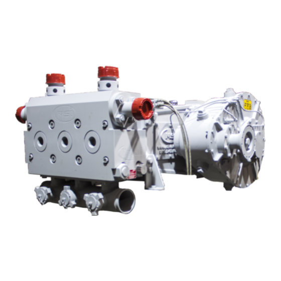
- Page 7 1.20 Drawings - Pump Assembly Overall Dimensions (All Plunger Sizes) TI-600 (TRIPLEX)
- Page 8 QI-1000 (QUINTUPLEX)
- Page 9 1.30 Dual Pump Assembly Overall Dimensions 1.30.1 600 HP Dual Pump Assembly Overall Dimensions...
- Page 10 1.30.2 1000 HP Dual Pump Assembly Overall Dimensions...
- Page 11 1.50 Drawings - Gear Reducer Installation Positions 1.50.1 Gear Reducer Position-Left Hand...
- Page 12 1.50.2 Gear Reducer Position Right Hand...
- Page 13 1.60 600 HP Pump Performance Data PLUNGER 2.75 3.00 3.25 3.50 4.00 4.50 GAL/REV 0.46 0.55 0.65 0.75 0.98 1.24 15,000 15,000 11,020 11,020 8,438 6,667 15,000 15,000 11,020 11,020 8,438 6,667 9,999 8,402 7,159 6,173 4,726 3,734 6,666 5,601 4,773 4,115 3,151...
- Page 14 1.70 1000 HP Pump Performance Data PLUNGER 2.75 3.00 3.25 3.50 4.00 4.50 GAL/REV 0.77 0.92 1.08 1.25 1.63 2.07 15,000 15,000 11,020 11,020 8,438 6,667 15,000 15,000 11,020 11,020 8,438 6,667 9,999 8,402 7,159 6,173 4,726 3,734 1,000 6,666 5,601 4,773 4,115...
- Page 15 2.00 Operation and Maintenance When determining the design of the pump installation, clearance is recommended for inlet and outlet connections as well as providing for a pressure relief device for the discharge line. A pressure relief device is required for all applications of this pump. Failure to implement a pressure relieving device may result in significant damage to the pump and attached piping, serious injury or death of personnel, and will void the pump warranty.
-
Page 16: Initial Inspection
90 and 95 on the dial. Tighten as necessary, but do not surpass 95 on the dial. If the indicator is not working return it to MSI for immediate replacement. Note: In order to achieve the necessary preload without damaging the bolt, DOW CORNING G-n Metal Assembly Paste must be used. - Page 17 90 and 95 on the dial. Tighten as necessary, but do not exceed 95 on the dial. If the indicator is not working return it to MSI for immediate replacement. Note: In order to achieve the necessary preload without damaging the bolt, use DOW CORNING G-n Metal Assembly Paste as a thread lubricant.
- Page 18 3.50 Every 250 hours Preventative Maintenance Check all items on “daily,” “weekly,” and “100 hours” list. Change the Power Frame lube oil and refill with the proper grade of gear oil for upcoming ambient conditions. Thoroughly clean the Power Frame lube suction strainer. Remove and inspect the plungers and packing assembly components.
-
Page 19: Lubrication Requirements: Power Train And Plungers
Lubrication Capacity Requirements The MSI Well Service Pump is a dry sump, i.e., it is not intended to contain a volume of lubricating oil. A separate lubrication oil reservoir is required with a 50 gallon minimum capacity; it should be installed below the plunger pump power end. - Page 20 Typical Lubrication Schematic A typical power end and gear reducer lubrication oil schematic is shown below. ITEM # DESCRIPTION RESERVOIR, VENTED 50 GALLON MIN CAPACITY SUCTION LINE, PIPE OR HOSE, 1 1/2” ID MINIMUM SUCTION STRAINER, 50 GPM MIN. 300 SQ IN MIN. 40-100 MESH w/3-5 PSI RELIEF CHECK VALVE, SWING, 1 1/2”...
-
Page 21: Lubrication Filtration
The MSI Well Service Pump is designed to prevent migration of well service fluids into the lubrication system. However, even with the MSI Well Service Pump there is still a need for an effective filtering system since contamination can come from other locations. Using a properly sized oil filter on your system and changing the filters regularly will significantly reduce downtime and maintenance costs. - Page 22 Lubrication Attachment Points See images below showing lubrication inlet and outlet locations.
- Page 23 Fluid End Plunger and Packing Lubrication Requirements It is essential for the effectiveness and life of the plunger packing to provide sufficient lubrication to the fluid end plungers and stuffing Reducer. Failure to do so may result in short packing life, plunger damage, and costly downtime.
- Page 24 4.10 Power Frame Lube Lines- Dual Lube Pipe QTY. PART NUMBER DESCRIPTION FC0146 NIPPLE, 1/2”NPT HEX x 02” PEC0051 HOSE ASSEMBLY, LUBRICATOR x 12” PEC0052 ROTOSEAL, LUBRICATOR PEC0053 HOSE ASSEMBLY, LUBRICATOR INTERNAL x 16.50” PEC0054 HOSE ASSEMBLY, LUBRICATOR INTERNAL x 9.50” TC0094 TEE BODY, 1/2”NPT FFF...
- Page 25 4.20 Gear Reducer Lube Lines ITEM NUMBER QTY. PART NUMBER DESCRIPTION UC0301 BLANK PLUG, 1/4" NPT SOCKET TYPE HIGH PRESS (5000psi) GRC0028 HOSE ASSEMBLY, LUBE PIPE (600HP) x 7.5" GRC0029 HOSE ASSEMBLY, PINION CAP (600HP) x 15.75" GRC0030 HOSE ASSEMBLY, PINION RETAINER (600HP) x 6" GRC0031 HOSE ASSEMBLY, BEARING COVER (600HP) x 11.5"...
- Page 26 5.00 Power Frame Repair Procedures Due to the complexity of the task and the need for special tools and training, MSI does not recommend the complete disassembly of the Power Frame in the field. If extensive Power Frame repairs are required, the pump should be returned to Dixie Iron Works, Ltd.
- Page 27 5.10.2 Reciprocating Assembly- Exploded ITEM # DESCRIPTION PART# CONNECTING ROD PEC0057 CONNECTING ROD BEARING PEC0044 CONNECTING ROD BOLT PEC0048 CONNECTING ROD NUT HC0086 CONNECTING ROD PIN HC0105 COTTER PIN HC0088 CROSSHEAD PEC0055 CROSSHEAD BEARING PEC0029 CROSSHEAD PIN PEC0013 CROSSHEAD RETAINER PEC0021 CROSS HEAD RETAINER BOLT HC0024...
- Page 28 5.10.3 Power Frame Assembly - Main Bearing Assembly ITEM NUMBER QTY. PART NUMBER DESCRIPTION HC0085 HEX NUT, 7/8"-9 HC0087 FLAT WASHER, 7/8" HARDENED PEC0031 GASKET, MAIN BEARING HOUSING (600/1000HP) PEC0063 MAIN BEARING HOUSING, (600/1000HP)
- Page 29 5.10.4 Power Frame Assembly-Oil Pan Collector ITEM 600 HP 600 HP DESCRIPTION NUMBER PART# PART # HC0015 HC0015 HEX HD, 3/8”-16 x1.00” HC0099 HC0099 LOCK WASHER, 3/8” STD PEC0065 PEC0099 OIL COLLECTOR ASSEMBLY...
- Page 30 5.10.5 Power Frame Assembly - Foot Assembly ITEM QTY. PART # DESCRIPTION NUMBER LEFT RIGHT HC0108 HEX HD, 3/4"-10 x 1.50" HC0134 FLAT WASHER, 3/4" SAE "N" UNDERSIZED PEC0187 PEC0186 FRONT FOOT, (600/1000HP) CENTERED RIB...
- Page 31 5.10.6 Power Frame Assembly - Side Cover ITEM NUMBER QTY. PART NUMBER DESCRIPTION HC0002 FLAT WASHER, 3/8” STD HC0004 HEX HD, 3/8"-16 x 0.75" PEC0078 SIDE COVER PEC0079 GASKET...
- Page 32 5.10.7 Power Frame Assembly-Breather/Drain Port Assembly ITEM NUMBER QTY. PART NUMBER DESCRIPTION HC0015 HEX HD, 3/8”-16 x 1.00” PEC0190 BREATHER PEC0083 GASKET PEC0189 BREATHER PORT PEC0085 DRAIN PORT...
- Page 33 5.10.8 Power Frame Assembly - Rear Cover ITEM 600 HP 1000 HP DESCRIPTION NUMBER PART# QTY. PART # HC0002 HC0002 FLAT WASHER, 3/8” STD HC0004 HC0004 HEX HD, 3/8”-16 x 0.75” PEC0077 PEC0095 REAR COVER PEC0080 PEC0096 GASKET...
- Page 34 5.10.9 Power Frame Assembly - Bearing Retainer ITEM NUMBER QTY. PART # DESCRIPTION PEC0060 BEARING RETAINER HC0015 HEX HD, 3/8”-16 x 1.00”...
- Page 35 5.20 Power Frame Assembly-Section View ITEM 600HP 1000HP DESCRIPTION NUMBER QTY. PART # QTY. PART # PEC0056 PEC0056 CROSSHEAD GUIDE PEC0062 PEC0088 CRANKSHAFT PEC0046 PEC0046 BEARING, INSIDE MAIN BEARING, FIXED PEC0047 PEC0047 BEARING, INSIDE MAIN BEARING, FLOAT PEC0057 PEC0057 CONNECTING ROD ASSEMBLY PEC0055 PEC0086 CROSSHEAD...
- Page 37 5.30 Removing the Crankshaft, Connecting Rods, and Crossheads Remove the Gear Reducer assembly (see Section 7.10.) Remove the plunger and seal retainers (see Section 6.30.) Using a 9/16” wrench, remove the 3/8” cap screws, which secure the side and rear covers to the Power Frame housing.
- Page 38 PEC0052 PEC0052 ROTOSEAL, LUBRICATOR (600HP & 1000HP) UC0050 UC0050 BLANK PLUG, 1/2” NPT STD (SOCKET) PEC0064 PEC0064 SPACER, CRANKSHAFT MSI 600 & 1000 TC0094 TC0094 TEE BODY, 1/2” NPT FFF PEC0051 PEC0051 HOSE ASSEMBLY, LUBRICATOR (600HP) x 12” Note: Long...
- Page 39 5.50 Power Frame Crank Rotation NOTE: Crank Rotation can either be clockwise or counterclockwise.
- Page 40 6.00 Fluid End Repair Procedures Exercise care while working on the Fluid End. Errant dings on the sealing surfaces of the Fluid End may cause leaks.
- Page 41 6.10 Fluid End Assembly- 2.75”-3.00” ITEM DESCRIPTION PART NUMBER ITEM DESCRIPTION PART NUMBER 2.75” 3.00” 2.75” 3.00” BACK-UP RING, SB FE SIDE OC0077 STUFFING Reducer FEC0066 FEC0010 ADAPTER BACK-UP RING, SB PE SIDE OC0077 OC0064 SUCTION COVER CAGE FEC0252 SUCTION COVER CAGE NUT FLUID END ADAPTER FEC0090 HC0132...
- Page 42 6.20 Fluid End Assembly- 3.25” -4.50” ITEM DESCRIPTION PART NUMBER 3.25” 3.50” 4.00” 4.50” BACK-UP RING, SB FE SIDE OC0066 BACK-UP RING, SB PE SIDE OC0139 OC0067 OC0070 OC0072 DISCHARGE COVER NUT FEC0005 FLUID END ADAPTER FEC0009 FLUID END PLUNGER FEC0259 FEC0056 FEC0057...
- Page 43 Fluid End Assembly- 3.25” -4.50”, continued...
- Page 44 6.30 Packing Assembly The following drawings depict the parts of the Packing Assembly and how the parts are made-up together. 6.30.1 Packing Assembly Plunger-Exploded View ITEM QTY. PART NUMBER DESCRIPTION 2.75” 3.00” 3.50” 4.00” 4.50” FEC0090 FEC0009 ADAPTER FLUID END OC0076 OC0065 O-RING, STUFFING Reducer, FE SIDE...
- Page 45 6.40 Removing Plungers and Packing Remove the plunger lube fitting from each packing nut. Using the MSI packing nut tool (FEC0027), loosen each of the packing nuts at least one full turn. Remove the suction covers using MSI Wrench (FEC0024).
- Page 46 6.41 Packing Tool Remover in Fluid End PUMP SIZE PART # DESCRIPTION 2.75” FEC0115 TOOL, ADAPTER RING RETAINER 600 - 2.75" 3.00” FEC0116 TOOL, ADAPTER RING RETAINER 600 - 3.00" 3.50” FEC0117 TOOL, ADAPTER RING RETAINER 600 - 3.50" 4.00” FEC0118 TOOL, ADAPTER RING RETAINER 600 - 4.00"...
- Page 47 6.50 Removing the Valves and Seats Using the MSI 2” hex cover wrench (MSI Wrench FEC0024) and a 10 lb. hammer, remove the suction covers and discharge covers from the fluid cylinder. Turn the suction valve stop until it stops approximately 90 degrees and remove the valve stops from the fluid cylinder along with the valve springs underneath them.
- Page 48 Inspect the face and O.D. of the pipe at each end of the manifold for erosion and corrosion. Note: The MSI manifold incorporates a Victaulic “ES” type connection at each end which will accept either a Victaulic “End Seal Cut Groove: gasket or a Victaulic “Standard Cut Groove”...
- Page 49 7.00 Gear Reducer Repair Procedures Due to the complexity of the task and the need for special tools and training, MSI does not recommend the complete disassembly of the Gear Reducer in the field. If extensive Gear Reducer repairs are required, the pump should be returned to the Dixie Iron Works, Ltd.
- Page 50 unit can be used to safely heat the bearings. When heating a bearing for installation, the temperature must not exceed 250 degrees Fahrenheit (121 degrees Celsius). Installation of new tapered roller bearing cups in the housing should be performed by tapping them into the housing with a soft metal bar or by pressing them into the housing.
- Page 51 7.20 Gear Reducer, 4.61:1 Ratio Standard- Exploded View ITEM QTY PART DESCRIPTION ITEM QTY PART # DESCRIPTION GRC0001 LARGE GEAR GRC0042 RETAINER WASHER GRC0002 GEAR CASE GRC0158 MANIF. BLOCK, 1/4"NPT x 6 GRC0020 PINION CAP HC0024 HEX HD, ½”-13 x 1.25” GRC0021 PINION SHAFT HC0032...
- Page 52 The resulting erosion of components, and cyclical stresses into the flow lines as a result of vibrations, can be a serious hindrance to the safety and suitable operation of a well service package design. MSI therefore recommends the use of a centrifugal charge pump as part of a properly designed supply system.
- Page 53 Appendix 9.00 Pump Formulas Definition of Symbols Used: Area (sq. in.) Brake horsepower Barrels per minute (U.S.) Flow velocity (ft./sec.) Gallons per minute (U.S.) Gallons per revolution (U.S.) Hydraulic horsepower Inside diameter (inches) Mechanical efficiency Number of cylinders (per pump) Plunger diameter (inches) Lbs./sq.
- Page 54 Pump Formulas To calculate the HHP output when the volume and pressure are known: To calculate the BHP input required when the volume, pressure, and mechanical efficiency are know: To calculate the maximum possible pressure when the BHP, flow, and ME are known: To calculate the maximum possible flow when the BHP, PSI, and ME are known: To calculate rod load when the plunger diameter, and pressure are known: To calculate the maximum possible pressure at a given rod load when the RL rating and plunger...
- Page 55 To calculate the internal size of piping required to maintain a specified flow velocity when the GPM and desired flow velocity are known: To calculate the maximum allowable GPM through a specified flow velocity when the internal area of the pipe and the desired flow velocity are known: To calculate pinion shaft or driveline torque when the input BHP and pinion shaft RPM are known: 9.10...
- Page 56 Each has a mechanical indicator in the face and should read between 90 and 95 on the dial. Tighten as necessary, but do not exceed 95 on the dial. If the indicator is not working return it to MSI for...
Need help?
Do you have a question about the TI-600 and is the answer not in the manual?
Questions and answers