
Subscribe to Our Youtube Channel
Related Manuals for MSI Hybrid Triplex

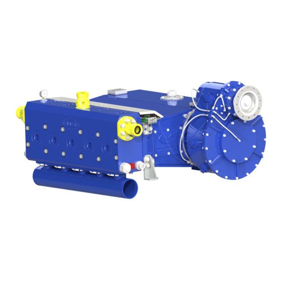
Summary of Contents for MSI Hybrid Triplex
- Page 1 Technical Manual MSI Hybrid™ Well Service Pump Triplex and Quintuplex Models MSI – A Division of Dixie Iron Works, Ltd. 300 W. Main St. Alice, TX 78332 www.diwmsi.com (800) 242-0059 Revision K...
-
Page 2: Table Of Contents
TABLE OF CONTENTS SECTION 1 WARNINGS ........................1 SECTION 2 GENERAL DESCRIPTION .................... 2 ......................... 2 ESCRIPTION ........................2 PECIFICATIONS ........................3 ERFORMANCE SECTION 3 PRESERVATION ......................7 ....................7 RESERVATION ONSIDERATIONS ......................7 RESERVATION FOR HIPPING ......................7 RESERVATION FOR TORAGE ....................... - Page 3 ..................41 AILY REVENTATIVE AINTENANCE ........................ 41 EEKLY AINTENANCE 100 H ......................... 41 VERY OURS 250 H ......................... 41 VERY OURS ..........42 EARLY OR AS ECOMMENDED REVENTATIVE AINTENANCE ..................42 NSPECTION OF EARINGS AND EARS SECTION 8 SPARE PARTS LIST, EXPENDABLES ..............43 ....................
-
Page 4: Warnings
SECTION 1 WARNINGS The MSI Hybrid™ Well Service Pump is used in high-pressure and high flow well service applications. High pressure equipment, if not used and maintained properly, can cause serious injury or death and damage to equipment and property. Not taking proper precautions and failing to perform routine maintenance and inspections can also contribute to loss of well control, and such loss could cause serious injury or death and damage to equipment and property. -
Page 5: General Description
The MSI Hybrid™ Well Service Pump is rated for pumping fluids up to 15,000 PSI or at flow rates up to 929 GPM. With different materials it can handle many fluid types, including abrasive and corrosive fluids. Seals are also available for low temperature and CO applications. -
Page 6: Pump Performance
Pump Performance The MSI Hybrid™ Well Service Pump can be equipped with 2.75", 3.00", 3.25", 3.50", 4.00", or 4.50" diameter fluid end plungers. There are two Xtreme Service™ fluid end sizes, one accommodates plunger sizes 2.75" – 3.00", and the other accommodates plunger sizes 3.25" – 4.50". See following pages for performance tables and curves. - Page 7 3,182 2,744 2,100 1,660 TIH-600 BHP 16,000 14,000 12,000 10,000 2.75 3.00 8,000 3.25 3.50 6,000 4.00 4.50 4,000 2,000 Flow Rate (GPM) Revision K 03/12/2019 MSI - A Division of Dixie Iron Works, Ltd. All rights reserved. Page 4...
- Page 8 2,744 2,100 1,660 QIH-1000 BHP 16,000 14,000 12,000 10,000 2.75 3.00 8,000 3.25 3.50 6,000 4.00 4.50 4,000 2,000 1000 Flow Rate (GPM) Revision K 03/12/2019 MSI - A Division of Dixie Iron Works, Ltd. All rights reserved. Page 5...
- Page 9 3,567 2,731 2,158 QIH-1300 BHP 16,000 14,000 12,000 10,000 2.75 3.00 8,000 3.25 3.50 6,000 4.00 4.50 4,000 2,000 1000 Flow Rate (GPM) Revision K 03/12/2019 MSI - A Division of Dixie Iron Works, Ltd. All rights reserved. Page 6...
-
Page 10: Preservation
Preservation for Storage If your new MSI Hybrid™ Well Service Pump, as packaged from MSI, will be in storage for longer than one month, then the following preservation measures should be taken: After taking delivery of the pump, remove the top of the shipping crate for pump inspection; be careful to not damage the crate. - Page 11 If a covering is not available, the pump should be covered and tied with a heavy duty tarp. Revision K 03/12/2019 MSI - A Division of Dixie Iron Works, Ltd. All rights reserved. Page 8...
-
Page 12: Preservation Between Jobs
Wear proper protection when working with compressed air on the inside of the fluid end. Covering all exposed discharge or suction openings will help in further preventing ingress of moisture to the pump. Revision K 03/12/2019 MSI - A Division of Dixie Iron Works, Ltd. All rights reserved. Page 9... -
Page 13: Installation
SECTION 4 INSTALLATION Pump Dimensions, CG, Lifting Points, and Mounting Requirements See drawings and photographs on following pages. Revision K 03/12/2019 MSI - A Division of Dixie Iron Works, Ltd. All rights reserved. Page 10... - Page 14 2 3/4" 3/4"-10 UNC 3/4" 2 1/4" 27" 20 3/4" 44 1/4" 23 3/8" SINGLE DIMENSIONS: TRIPLEX OR QUINTUPLEX DUAL DIMESIONS: TRIPLEX QUINTUPLEX Revision K 03/12/2019 MSI - A Division of Dixie Iron Works, Ltd. All rights reserved. Page 11...
- Page 15 CG IS APPROXIMATE FOR COMMON CONFIGURATIONS FOR EITHER THE TRIPLEX OR QUINTUPLEX PUMP, DIFFERENT GEAR POSITIONS AND PLUNGER SIZES WILL MOVE THE CG SLIGHTLY Revision K 03/12/2019 MSI - A Division of Dixie Iron Works, Ltd. All rights reserved. Page 12...
- Page 16 The pump CG are shown in the previous drawings. Use only properly rated lifting harnesses for installation, removal, and maintenance of the MSI Hybrid™ Well Service Pump. Please note that the weights listed on the following pages are average weights based on typical pump configurations. Please contact MSI for configuration-specific weights.
- Page 17 Use 2" MNPT bull plug tapped to accept rated lifting eyes. TIH-600 Gear Reducer Wt ~ 900 LBS QIH-1000/1300 Gear Reducer Wt ~ 1200 LBS Revision K 03/12/2019 MSI - A Division of Dixie Iron Works, Ltd. All rights reserved. Page 14...
- Page 18 Use MSI lifting sub LSA0001. TIH-600 Fluid End Wt ~ 1600 LBS QIH-1000/1300 Fluid End Wt ~ 2500 LBS Revision K 03/12/2019 MSI - A Division of Dixie Iron Works, Ltd. All rights reserved. Page 15...
-
Page 19: Maintenance Space Requirements
MSI has provided a combination weather cover and safety guard for the plunger access ports. The cover additionally serves to store tools specific to the MSI Hybrid™ Well Service Pump. It is the responsibility of the packager to design the unit in such a way that this equipment is intact and functional. - Page 20 DENOTED BY * SHOULD BE PROVIDED IN ANY CONFIGURATION FOR ACCESS TO COMMONLY REPLACED ITEMS SUCH AS VALVES, VALVE SEATS, PACKING, AND SEALS. Revision K 03/12/2019 MSI - A Division of Dixie Iron Works, Ltd. All rights reserved. Page 17...
-
Page 21: Pump Service Tools
Special tools are required to perform routine maintenance such as replacing packing, valves & seats, plungers, and seals. See drawing on next page for available tools. MSI Hybrid™ Well Service Pump Enhancement – The packing nut tool is conveniently located on the plunger access port weather cover. It is securely mounted and provides at-the-ready accessibility, eliminating downtime caused by lost or misplaced tools. - Page 22 SMALL BORE: FEC0113 LARGE BORE: FEC0114 HYDRAULIC VALVE SEAT PULLER UNIVERSAL: HSPA001 VALVE COVER TOOL UNIVERSAL: FEC0024 CONTACT MSI SALES FOR OPTIONS AND PARTS LISTS Revision K 03/12/2019 MSI - A Division of Dixie Iron Works, Ltd. All rights reserved. Page 19...
-
Page 23: Pump Drive Connections And Locations
The driveline shaft must include a slip joint with 1" minimum slip in the joint after installation. Revision K 03/12/2019 MSI - A Division of Dixie Iron Works, Ltd. All rights reserved. Page 20... - Page 24 LEFT HAND 15 LEFT HAND 16 LEFT HAND 13 LEFT HAND 14 STANDARD GEAR REDUCER (4.61:1 REDUCTION RATIO) *POSITION DIMENSIONS ROUNDED TO THE NEAREST 1/16" Revision K 03/12/2019 MSI - A Division of Dixie Iron Works, Ltd. All rights reserved. Page 21...
- Page 25 RIGHT HAND 15 RIGHT HAND 16 RIGHT HAND 14 RIGHT HAND 13 STANDARD GEAR REDUCER (4.61:1 REDUCTION RATIO) *POSITION DIMENSIONS ROUNDED TO THE NEAREST 1/16" Revision K 03/12/2019 MSI - A Division of Dixie Iron Works, Ltd. All rights reserved. Page 22...
- Page 26 LEFT HAND 14 15 1/4" 6 5/16" LONG DRIVE (UNDER/OVER DRIVE) GEAR REDUCER (4.61:1 REDUCTION RATIO) *POSITION DIMENSIONS ROUNDED TO THE NEAREST 1/16" Revision K 03/12/2019 MSI - A Division of Dixie Iron Works, Ltd. All rights reserved. Page 23...
- Page 27 RIGHT HAND 13 RIGHT HAND 14 15 1/4" LONG DRIVE (UNDER/OVER DRIVE) GEAR REDUCER (4.61:1 REDUCTION RATIO) *POSITION DIMENSIONS ROUNDED TO THE NEAREST 1/16" Revision K 03/12/2019 MSI - A Division of Dixie Iron Works, Ltd. All rights reserved. Page 24...
-
Page 28: Fluid Pumping Connections And Pressure Relief Considerations
3.50” 11,020 psig 4.00” 8,438 psig 4.50” 6,667 psig See drawing on following page for piping location dimensions and pressure relief mounting locations. Revision K 03/12/2019 MSI - A Division of Dixie Iron Works, Ltd. All rights reserved. Page 25... - Page 29 TYPICAL INSTALLATION: RELIEF DEVICE & DISCHARGE PLUMBING LOW PRESSURE INLET EITHER OR BOTH ENDS VICTAULIC TYPE CONNECTION DEPICTED CONSULT FACTORY FOR OTHER OPTIONS Revision K 03/12/2019 MSI - A Division of Dixie Iron Works, Ltd. All rights reserved. Page 26...
-
Page 30: Pump Lubrication And Instrument Connections
Pump Lubrication and Instrument Connections Pump pressure, RPM, oil pressure, and oil temperature instruments and safety controls are recommended. See drawings on following pages. Revision K 03/12/2019 MSI - A Division of Dixie Iron Works, Ltd. All rights reserved. Page 27... - Page 31 POWERTRAIN LUBE OIL INLET, THIS SIDE OR OPPOSITE SIDE USING BOTTOM INLET PORT, 1/2" FNPT. PLUG UNUSED SIDE WITH 1/2" MNPT PIPE PLUG. Revision K 03/12/2019 MSI - A Division of Dixie Iron Works, Ltd. All rights reserved. Page 28...
-
Page 32: Plunger Auto-Lube And Relief System
(PTO) from the crankshaft. This approach to determining lubrication cycles eliminates over or under lubricating and ensures lubricant is supplied whenever the pump is in motion. The Auto-Lube™ System can be used in conjunction with the MSI Lube Relief System™ to provide outstanding lubrication performance. -
Page 33: Charge Pump Intake
MSI therefore recommends the use of a centrifugal charge pump as part of a properly designed supply system. Well service pump cavitations will occur if the pump suction pressure drops to a level approaching the vapor pressure of the fluid being pumped. -
Page 34: Pump Discharge Requirements
Never operate this MSI pump without a suitable pressure relief device set for the maximum pressure that the well service pump and all connected piping and equipment can be safely operated. -
Page 35: Lubrication Requirements: Power Train And Plungers
Lubrication Capacity Requirements The MSI Hybrid™ Well Service Pump is a dry sump, i.e., it is not intended to contain a volume of lubricating oil. A separate lubrication oil reservoir is required with a 50 gallon minimum capacity; it should be installed below the plunger pump power end. -
Page 36: Typical Lubrication Schematic
Typical Lubrication Schematic A typical power end and gear reducer lubrication oil schematic is shown on the following page. Revision K 03/12/2019 MSI - A Division of Dixie Iron Works, Ltd. All rights reserved. Page 33... - Page 37 POWER END LUBE DRAIN, 3" NPTM GEAR REDUCER DRAIN, 2" NPTF TEMPERATURE TRANSDUCER/GUAGE, 0-250 F SUPPLY FLOW OPTIONAL SEE SECTION 5.3 RETURN FLOW Revision K 03/12/2019 MSI - A Division of Dixie Iron Works, Ltd. All rights reserved. Page 34...
-
Page 38: Heat Generation, Dissipation And Cooling
Lubrication Relief Valve A relief valve should be part of any MSI Hybrid™ Well Service Pump lubrication system. MSI recommends a relief valve that is rated for 20-25 GPM and 60-200 PSI to relieve excess pressure which could damage filters, lines, gauges, or other connected equipment. -
Page 39: Lubrication Attachment Points
Consult MSI Engineering if assistance is required in selecting a lubricant. Oil Change and Oil Types MSI recommends that oil condition be monitored, and samples should be tested by a certified laboratory to determine the optimum frequency for oil changes. Laboratory testing can also aid in identifying pump damaging particles that may originate from unsuspected sources such as low quality lubricants or filters. -
Page 40: Cleaning Plunger Lubrication Drip Pan
The drip pan is intended to collect plunger lubricant that bypasses the sealing element. To clean the pan remove the screws and slide the pan out from below the pump. Clean then reinstall it. Revision K 03/12/2019 MSI - A Division of Dixie Iron Works, Ltd. All rights reserved. Page 37... -
Page 41: Start-Up And Shut-Down
Replace immediately if the tension indicator is not functioning. *If your MSI Hybrid™ Well Service Pump is equipped with an Xtreme style fluid end, it will have large Maxbolts™ installed longitudinally through the fluid end. The tension on these bolts is pre-set at the factory and should not need adjustment. - Page 42 The packing in this pump is non-adjustable; therefore, fully tightening the packing nut is required to properly set the gland length. See Section 9.2 for instructions on this. Revision K 03/12/2019 MSI - A Division of Dixie Iron Works, Ltd. All rights reserved. Page 39...
-
Page 43: Shut-Down Procedure
4) Close any valves necessary to isolate the pump from well service fluid in the circulation tank. 5) Leave the prime mover running so that oil to the MSI Hybrid™ Well Service Pump will continue to circulate and cool down any internal parts that were under heavy load prior to the shut-down. -
Page 44: Preventative Maintenance
Every 250 Hours Check all items on “daily,” “weekly,” and “100 hours” list. Revision K 03/12/2019 MSI - A Division of Dixie Iron Works, Ltd. All rights reserved. Page 41... -
Page 45: Yearly, Or As Recommended, Preventative Maintenance
Inspection of the gears, bearings, and journal bearings should be made every 500 hours. Check the oil filter for telltale signs, such as flaking metal. Also, check for end play on the pinion shaft, see Section 10.2. Revision K 03/12/2019 MSI - A Division of Dixie Iron Works, Ltd. All rights reserved. Page 42... -
Page 46: Spare Parts List, Expendables
SPARE PARTS LIST, EXPENDABLES Recommended Spare Parts List MSI recommends that at a minimum the following spare parts be available during pump operation. See Section 9 for size specific part numbers. Contact MSI for availability of expendables packages for all plunger sizes. -
Page 47: Fluid End
SECTION 9 FLUID END Detail Section Drawings, Service Tools See drawings on following pages. Revision K 03/12/2019 MSI - A Division of Dixie Iron Works, Ltd. All rights reserved. Page 44... - Page 48 HC0454 VALVE FEC0504 (INSERT FEC0504-I) VALVE SEAT FEC0453 VALVE SPRING FEC0093 VALVE STOP ASSEMBLY FEC0382 DOWEL PIN HC0507 RETENTION SCREW HC0946 DETAIL A Revision K 03/12/2019 MSI - A Division of Dixie Iron Works, Ltd. All rights reserved. Page 45...
- Page 49 HC0454 VALVE FEC0472 (INSERT FEC0472-I) VALVE SEAT FEC0473 VALVE SPRING FEC0003 VALVE STOP ASSEMBLY FEC0383 DOWEL PIN HC0507 RETENTION SCREW HC0946 DETAIL A Revision K 03/12/2019 MSI - A Division of Dixie Iron Works, Ltd. All rights reserved. Page 46...
-
Page 50: Replacing Fluid End Plunger And Packing
10 lb. hammer. Replace cover nut seal if damaged. MSI Hybrid™ Well Service Pump Enhancement – The suction cover nuts consist of a thread half and a gland half and are attached with a shoulder screw to allow one piece extraction yet also allow the two parts to rotate independently. - Page 51 Replace as required. MSI Hybrid™ Well Service Pump Enhancement – It is not necessary to use special tools to retain the stuffing box adapter (junk ring) in the fluid end. There is sufficient space to leave the ring in the packing nut and extract through the packing service port.
- Page 52 14) Reinstall the suction covers using the valve cover tool and a 10 lb. hammer. 15) Slide the safety cover back over the packing access ports and re-tighten the screws. Revision K 03/12/2019 MSI - A Division of Dixie Iron Works, Ltd. All rights reserved. Page 49...
- Page 53 ARRESTING FEATURES OF THE USING PACKING NUT TOOL OPERATION IN THIS CASE. FLUID END ADAPTER. PACKING NUT READY FOR REMOVAL IN THIS CASE. HC0946 RETENTION SCREW Revision K 03/12/2019 MSI - A Division of Dixie Iron Works, Ltd. All rights reserved. Page 50...
-
Page 54: Replacing Valves And Seats
10 lb. hammer. MSI Hybrid™ Well Service Pump Enhancement – The suction cover nuts consist of a thread half and a gland half and are attached with a shoulder screw to allow one piece extraction yet also allow the two parts to rotate independently. - Page 55 MSI fluid end. Using valve components not supplied by MSI can result in rough operation of the pump due to insufficient fluid flow area around the valve. Insufficient flow area will result in excessive turbulence, cavitations, damaging vibrations, and premature wear of the fluid end and its internal components.
- Page 56 LIFT SPRING TOWARDS CENTER OF BORE TO DISENGAGE LOCK AND ALLOW VALVE STOP REMOVAL Revision K 03/12/2019 MSI - A Division of Dixie Iron Works, Ltd. All rights reserved. Page 53...
-
Page 57: Discharge Connections And Inspection Requirements
NOTE: If sand, cement, or other solids were used in the last well service job, all manifold lines need to be cleared, cleaned, and inspected. See MSI Minimum Wall Chart (Dixie Engineering Specification 9- 2014) for inspecting MSI flow control components. Also, clean out the fluid end and inspect all internal components and replace as needed. - Page 58 1000 BHP: FEC0146 1300 BHP: FEC0478 DISCHARGE FLANGES CAN BE PROVIDED WITH MALE OR FEMALE HAMMER UNIONS AND IN STRAIGHT OR ELBOW CONFIGURATIONS. Revision K 03/12/2019 MSI - A Division of Dixie Iron Works, Ltd. All rights reserved. Page 55...
-
Page 59: Suction Manifold And Connections
0.050" of material has been eroded or corroded from the inside of the manifold, replace the suction manifold. 7) Lightly grease the o-rings when reinstalling the manifold and torque the cap screws per Appendix Revision K 03/12/2019 MSI - A Division of Dixie Iron Works, Ltd. All rights reserved. Page 56... - Page 60 GROOVE CONNECTIONS NPS 4, 5, OR 6 STD NOTE: MANIFOLD SHOWN IS TYPICAL, OTHER SIZES AND CONFIGURATIONS ARE AVAILABLE, CONTACT MSI SALES FOR OPTIONS. Revision K 03/12/2019 MSI - A Division of Dixie Iron Works, Ltd. All rights reserved. Page 57...
-
Page 61: Replacing The Fluid End
8) Apply torque to the Maxbolts™ until the indicator reaches approximately 90%-95%. If the indicator is not working, replace the bolts with new ones obtained from MSI. CAUTION: Do not attempt to tighten the Maxbolts™ with a torque value. Use only the dial indicator to determine when the pre-load has been achieved, this is the most accurate method. - Page 62 11) Reconnect the discharge lines, pressure relief valve, and the instrument connection for the pressure transducer. 12) Follow the start-up procedure in Section 6.1 and check for leaks. Revision K 03/12/2019 MSI - A Division of Dixie Iron Works, Ltd. All rights reserved. Page 59...
- Page 63 FLUID END BOLT 1" HC0135 FLUID END BOLT 1 3/8" HC0136 2"1502 LIFTING SUB LSA0001 *AVAILABLE SEPARATELY QUINTUPLEX PUMP USES 12 OF THE HC0136 BOLTS Revision K 03/12/2019 MSI - A Division of Dixie Iron Works, Ltd. All rights reserved. Page 60...
-
Page 64: Gear Reducer
GEAR REDUCER Due to the need for special tools and special training, MSI does not recommend field repair of the gear reducer. If repairs are needed, the entire pump should be returned to an MSI repair facility. When field service of the gear reducer is needed, it should be completed in a clean, well equipped shop by a trained well service pump technician. - Page 65 * THE STANDARD TRIPLEX PUMP COMPANION FLANGE UTILIZES A SPICER SERIES 1810 CONNECTION, THE QUINTUPLEX PUMP UTILIZES A SPICER SERIES 1950 CONNECTION. INPUT FLANGE OPTIONS ARE AVAILABLE, CONTACT MSI SALES Revision K 03/12/2019 MSI - A Division of Dixie Iron Works, Ltd. All rights reserved. Page 62...
-
Page 66: Checking And Adjusting Bearing Pre-Load
7) Reinstall the pinion bearing retainer and torque screws per table in Appendix 8) Replace the companion flange. Apply Loctite® Threadlocker Blue and tighten cap screw just until washer slightly deflects (approx. 100 ft-lbs). Revision K 03/12/2019 MSI - A Division of Dixie Iron Works, Ltd. All rights reserved. Page 63... -
Page 67: Removal Of Gear Reducer And Bearing Housing
5) 3/4"-10 UNC tapped holes are provided in the gear reducer flange for using jack screws. 6) Pull the gear reducer away from the power end to disengage the main gear from the crankshaft. Revision K 03/12/2019 MSI - A Division of Dixie Iron Works, Ltd. All rights reserved. Page 64... - Page 68 FLAT WASHER, HARDENED HC0087 GASKET PEC0031 GEAR REDUCER GRA0001 GRA0003 HEX NUT HC0085 MAIN BEARING HOUSING PEC0063 BEARING HOUSING SEAL PEC0061 STUD BOLT HC0084 Revision K 03/12/2019 MSI - A Division of Dixie Iron Works, Ltd. All rights reserved. Page 65...
-
Page 69: Power End
The drive shaft and the windows containing the moving fluid end plungers and power end plungers must be covered with appropriate safety guards. GEAR REDUCER AND DRIVE SHAFT GUARD PLUNGER PORT SAFETY GUARD AND WEATHER SHIELD Revision K 03/12/2019 MSI - A Division of Dixie Iron Works, Ltd. All rights reserved. Page 66... -
Page 70: Removing And Lifting Of The Power End
If the power end requires rework, the well service truck or skid should be brought to an MSI repair facility. If the entire well service unit cannot be returned, then return the complete pump with the gear reducer and fluid end still attached. - Page 71 HC0004 ACCESS COVER WASHER HC0002 REAR ACCESS COVER PEC0077 PEC0095 REAR ACCESS GASKET PEC0080 PEC0096 SIDE ACCESS COVER PEC0078 SIDE ACCESS GASKET PEC0079 Revision K 03/12/2019 MSI - A Division of Dixie Iron Works, Ltd. All rights reserved. Page 68...
-
Page 72: Replacing Power End Plunger, Seal Housing, And Seals
Ensure it is not scored, scratched, or pitted. Replace the power end plunger if needed. MSI Hybrid™ Well Service Pump Enhancement – The power end plunger is the key element of the Hybrid pump design. It eliminates the shared sealing surface and positively prevents ingress of pumpage to the power end. - Page 73 18) Slide the safety cover back over the packing service ports and re-tighten the screws. 19) Empty, clean, and replace the plunger lubrication relief system reservoir. Revision K 03/12/2019 MSI - A Division of Dixie Iron Works, Ltd. All rights reserved. Page 70...
- Page 74 POWER END PLUNGER SCREW HC0467 WEATHER COVER POWER END PLUNGER LOCK WASHER HC0023 USE INSTALLATION TOOL TO GUIDE SEAL ONTO POWER END PLUNGER. Revision K 03/12/2019 MSI - A Division of Dixie Iron Works, Ltd. All rights reserved. Page 71...
-
Page 75: Replacing Crankshaft Journal Bearings And Connecting Rods
9.2. 2) Remove the access panels per Section 11.3. 3) Remove the power end plungers and seal housings per instructions in Section 11.4. Revision K 03/12/2019 MSI - A Division of Dixie Iron Works, Ltd. All rights reserved. Page 72... - Page 76 8) Reassemble in the reverse order of these instructions. MSI Hybrid™ Well Service Pump Enhancement – The crosshead pin retainer has been eliminated from this design since the pin is screwed securely to the connecting rod. Therefore the potential for catastrophic failure due to improper retainer installation has been completely eliminated.
- Page 77 CRANK ROTATION TANG PREVENTS BEARING ROTATION UNDER LOAD DIRECTION OF FORCE DETAIL A Revision K 03/12/2019 MSI - A Division of Dixie Iron Works, Ltd. All rights reserved. Page 74...
- Page 78 POWER END PLUNGER WASHER HC0023 A COMPLETE CROSSHEAD ASSEMBLY CAN BE ORDERED AS PEC0228 AND CONSISTS OF: (1) PEC0217 (1) PEC0219 (2) HC0503 (2) HC0504 Revision K 03/12/2019 MSI - A Division of Dixie Iron Works, Ltd. All rights reserved. Page 75...
-
Page 79: Replacing Crosshead Guides
Instead, apply Loctite® Threadlocker Blue and torque them to 50 ft-lbs. Do not apply excessive torque to the screws, doing so may distort the guides and cause damage to the pump if operated in that condition. Revision K 03/12/2019 MSI - A Division of Dixie Iron Works, Ltd. All rights reserved. Page 76... - Page 80 ITEM NO. DESCRIPTION PART NUMBER CROSSHEAD GUIDE PEC0056 CROSSHEAD GUIDE BOLT HC0083 COMPONENTS DEPICTED IN GENERAL DIRECTION OF REMOVAL Revision K 03/12/2019 MSI - A Division of Dixie Iron Works, Ltd. All rights reserved. Page 77...
-
Page 81: Appendix Atypical Pump Formulas
To calculate the maximum possible rate when the BHP, PSI, and ME are known: 1714 e. To calculate rod load when the fluid end plunger diameter and pressure are known: 7854 Revision K 03/12/2019 MSI - A Division of Dixie Iron Works, Ltd. All rights reserved. Page 78... - Page 82 3208 k. To calculate pinion shaft or driveline torque when the input BHP and pinion shaft RPM are known: 5252 Revision K 03/12/2019 MSI - A Division of Dixie Iron Works, Ltd. All rights reserved. Page 79...
- Page 83 0.004329 Gallons (U.S.) Cu. Ft./Sec. 448.831 0.002228 Cu. Ft./Sec. Head Feet (water) 0.4331 2.309 Head Feet (water) Kilowatts 1.341 Horsepower Horsepower 0.7457 Kilowatts Revision K 03/12/2019 MSI - A Division of Dixie Iron Works, Ltd. All rights reserved. Page 80...
-
Page 84: Appendix Btroubleshooting
Revision K 03/12/2019 MSI - A Division of Dixie Iron Works, Ltd. All rights reserved. Page 81... -
Page 85: Pump Running Rough
Ruptured suction stabilizer bladder, the bladder has lost its nitrogen charge, or the charge pressure was set too high. A properly charged suction stabilizer is set to 30-40% of the operating suction line Revision K 03/12/2019 MSI - A Division of Dixie Iron Works, Ltd. All rights reserved. Page 82... -
Page 86: Lubrication Vent Smoke
Failure of bushings, bearings, or gear teeth. Continuing to run the pump will cause expensive repairs. Vapor around the hot oil filler cap on a cold day. Revision K 03/12/2019 MSI - A Division of Dixie Iron Works, Ltd. All rights reserved. Page 83... -
Page 87: Appendix Cfastener Torque Data
Fluid End Plungers: Install plungers using anti-seize compound and torque to 375 ft-lbs of torque. Power End Plunger Screws: Install 1/2”-13 screws using Loctite® Threadlocker Blue and torque to 75 ft-lbs of torque. Revision K 03/12/2019 MSI - A Division of Dixie Iron Works, Ltd. All rights reserved. Page 84... - Page 88 MSI – A Division of Dixie Iron Works, Ltd. 300 W. Main St. Alice, TX 78332 www.diwmsi.com (800) 242-0059 (361) 664-6597...
Need help?
Do you have a question about the Hybrid Triplex and is the answer not in the manual?
Questions and answers