Table of Contents
Advertisement
Quick Links
Advertisement
Table of Contents

Subscribe to Our Youtube Channel
Summary of Contents for MGE UPS Systems UPS
- Page 1 w w w . m g e u p s . c o m Graphical Command Center User Manual...
-
Page 2: Important Safety Instructions
Graphical Command Center I M P O R TA N T S A F E T Y I N S T R U C T I O N S SAVE THESE INSTRUCTIONS – This manual contains important instructions for all GCC's that must be followed during operation of the equipment. - Page 3 Graphical Command Center User Manual For service call 1-800-438-7373 86-132204-00 A00 01/03 Copyright © 2002 MGE UPS SYSTEMS, Inc. All rights reserved. Printed in U.S.A. MGE UPS SYSTEMS, Inc. 1660 Scenic Avenue Costa Mesa, CA 92626 (714) 557-1636 page iii...
-
Page 4: Warranty
The liability of MGE UPS SYSTEMS, Inc. hereunder is limited to replacing or repairing at MGE UPS SYSTEMS, Inc.’s factory or on the job site at MGE UPS SYSTEMS, Inc.’s option, any part or parts which are defective, including labor, for a period of 12 months from the date of purchase. The MGE UPS SYSTEMS, Inc. -
Page 5: How To Use This Manual
How To Use This Manual: This manual is designed for ease of use and easy location of information. To quickly find the meaning of terms used within the text, look to the Glossary. To quickly find a specific topic, look at the Table of Contents. This manual uses icons with text to convey important information. - Page 6 Graphical Command Center (This page left blank intentionally) page vi...
-
Page 7: Table Of Contents
section Section 1 Introduction section Section 2 GCC Setup section 2.1.1 2.1.2 2.1.3 2.1.4 description ........page Important Safety Instructions . - Page 8 Menu Buttons ........3-2 UPS Status Panel ........3-4 System Main Menu Screen .
- Page 9 Section 5 GCC Alarms section description ......... . .page Section 6 GCC Troubleshooting section...
- Page 10 Input Screen ........3-14 S-M UPS Online ........4-2 S-M UPS on Bypass .
- Page 11 Figures (continued) number 6-10 Tables number description ........page Alarm/Event Present Log Screen .
- Page 12 Graphical Command Center (This page left blank intentionally) page c vi...
-
Page 13: Introduction
86-130033-00 EPS 6000 User Manual, 150-750kVA Single-Module 86-130034-00 EPS 6000 User Manual, 150-750kVA Multi-Module 86-131107-00 EPS 6000 User Manual, Parallel-Connected Single UPS Units 6739390XU EPS 6000 Communication Manual, 50/60 Hz Section Descriptions This manual is divided into six sections: Section 1 — Introduction This section is a general introduction and overview of the MGE Graphical Command Center (GCC). -
Page 14: Gcc System Overview
When powering up the display a boot screen similar to what you see in starting a “Windows PC” appears. The display will proceed with a memory test and other prerequisites, then load the operating system, and finally the UPS monitoring software. The GCC is ready when showing the mimic diagram with the menu selection buttons. -
Page 15: Keypad
Use the “<-” and “->” keys to scroll to next group of keys. See Figure 1-1 for all the available keypads. Press the “OK” key when done entering information. Use the “Esc” key to exit the keypad without saving informa- tion. Figure 1-1: Keypad Alphanumeric Characters. Keypad 1 UPS 1 + /- - > Keypad 4 - >... -
Page 16: Gcc Configurations
The GCC is located on the UPS Module, the Static Switch Cabinet or both. A Single-Module UPS configuration is shown in Figure 1-2. A Multi-Module UPS and SSC with a GCC on each UPS is shown in Figure 1-3. A Multi- Module UPS and SSC with one GCC on the SSC is shown in Figure 1-4. - Page 17 User Manual Figure 1-3: M-M Configuration, 1 GCC per each Module and the SSC. (800kVA UPS system shown) Figure 1-4: M-M Configuration, 1 GCC per system located on the SSC. (800kVA UPS system shown) Introduction page 1 — 5...
- Page 18 Graphical Command Center (This page left blank intentionally) page 1 — 6...
-
Page 19: Gcc Setup
User may change the password at that time or continue with the setup. Refer to section 1.4 Keypad for instruc- tions to use the keypad. Figure 2-1: Enter Setup Screen. 14:02:02 01/24/2003 Setup ALARMS UPS 1 manager Load Protected Inverter Enter Rectifier... -
Page 20: Identification Setup Screen
The Identification Setup screen is accessed from the Enter Setup screen when the password is entered. For a Single-Module the Identification Setup allows the User to modify the naming conventions for the UPS’s, circuit breakers, and inputs of the unit. For Multi-Module system the Identification Setup and System Configuration screens allow the User to modify the naming conventions. -
Page 21: S-M Identification Setup Screen
Battery Breaker Alarm Set to have Alarm Screen automatically Popup open when new Alarm/Event happens Screen Select if UPS is a 225, 300, 375 or 500KVA Figure 2-3: M-M Identification Setup Screen. 07:34:18 01/24/2003 System Name Setu p UPS 1 Name... -
Page 22: M-M System Configuration Screen
UPS 1 Present UPS 2 UPS 3 Set to have Alarm Screen automatically open when new Alarm/Event happens Select if UPS is a 225, 300, 375 or 500KVA GCC Setup UPS 4 UPS 5 UPS 6 Show battery Backup time... - Page 23 2.1.3 Change Password Change Password will allow the User to change the default password ‘manager’ to a new User password. NOTE: Proceed as follows: (Lower case and 20 characters maximum) 1. From the menu button click the Change Password button. 2.
- Page 24 Graphical Command Center 2.1.4 Control Panel The Control Panel is available to modify computer settings similar to a PC windows control panel. The date and time can be changed by double-clicking the Date/Time icon as shown in Figure 2-6. NOTE: Figure 2-6: Date and Time Icon.
-
Page 25: Change Password
SETUP IDENTIFICATION SETUP SYSTEM CONFIGURATION CHANGE PASSWORD CONTROL PANEL MULTI-MODULE SYSTEM SETUP MAIN MENU UPS 1 LOAD INPUT ALARMS/EVENTS ALARMS/EVENTS ALARMS PRESENT MAIN MENU GCC Screens User Manual G C C S c r e e n s ALARM TREND... -
Page 26: Main Menu Screen
Graphical Command Center Main Menu Screen The Main Menu Screen consists of three major components: the menu buttons, UPS status panel, mimic diagram. For Mimic Diagram, see section 4.0. 3.2.1 Menu Buttons The GCC uses menu button selections on the left side of each screen. For Single-Module selections see Figure 3- 1a. - Page 27 Alarms. Opens the corresponding UPS Main Menu Screen. The default names are UPS 1 to UPS 6, but can be changed in the Setup screen. See section 2.1.1 Enter Setup. The second and third line indicates the condition (status) of the system: “UPS Online”...
-
Page 28: Ups Status Panel
UPS Status Panel The UPS Status Panel is located at the top of the Main Menu screen. It consists of five items that give the User current information, such as, % load, alarms, battery backup time, name of UPS, and load status pertaining to the selected Single or Multi-Module UPS. -
Page 29: System Main Menu Screen
System Main Menu Screen The System Main Menu screen is shown for a three UPS Multi-Module system configuration in Figure 3-3. Up to 6 UPS modules can be displayed. Figure 3-3: M-M System Main Menu Screen. 07:51:39 Setu p Trend... -
Page 30: Inverter Screen
Three indicators are present to show inverter is connected to load, overload and out of synchronization with bypass status. The inverter indicators are displayed only when conditions are present. Figure 3-4: Inverter Screen. 13:41:27 01/24/2003 UPS 1 Setu p Voltage ALARMS UPS 1... -
Page 31: Rectifier Screen
Rectifier/Charger. See Figure 3-5. Figure 3-5: Rectifier Screen. 13:41:27 01/24/2003 Setu p ALARMS Utility 1 Voltage UPS 1 Rectifier/Charger Input Frequency Load Protected Rectifier/Charger Voltage Inverter Utility 1 Input Switch Battery Circuit Breaker... -
Page 32: Single-Module Load Screen
Single-Module Load Screen The Single-Module Load screen displays information such as voltage L-L and L-N, current, frequency, kW, kVA, pf, and % load. See Figure 3-6. Figure 3-6: S-M Load Screen. 13:40:17 UPS 1 01/24/2003 Setu p Voltage ALARMS UPS 1... -
Page 33: Multi-Module Load Ups Screen
Multi-Module Load UPS Screen The Multi-Module Load UPS screen is accessed from the UPS mimic diagram. The screen displays information of the selected UPS and overall system status, such as voltage, current, frequency, kW and kVA, pf, and % load. See Figure 3-7. -
Page 34: Multi-Module System Load Screen
The Multi-Module System Load screen is accessed from the system mimic diagram. The screen displays infor- mation on kW, %kW and %kVA of all the UPS’s configured, and the overall system measurements. See Figure 3-8. Figure 3-8: M-M System Load Screen. -
Page 35: Single-Module Battery Screen
The Single-Module Battery screen displays information such as DC voltage, discharge and charging current, and battery CB status. When enabled at the UPS, battery temperature and backup time are also available. Refer to Section 2.0 for Setup information. See Figure 3-9. -
Page 36: Multi-Module Battery Screen
Multi-Module Battery Screen The Multi-Module Battery screen displays Information such as DC Voltage, discharge and charging current, and battery CB status. When enabled at the UPS, battery temperature and backup are also available. See Section 2.0 for Setup information. See Figure 3-10. -
Page 37: Online Trending Screen
Clicking on the UPS 1 button will allow the User to enter the Main Menu screen. UPS 1 is the selected UPS module to be trended, but other UPS Modules can be selected from the Main Menu screen. -
Page 38: Input Screen
Graphical Command Center 3.12 Input Screen The Input screen allows the User to view all the input measurements such as voltage, current and frequency of the UPS's configured. See Figure 3-12. Figure 3-12: Input Screen. 11:57:27 Setu p Trend UPS 1... -
Page 39: Gcc Mimic Diagrams
Scope This section provides GCC mimic diagrams representing the common status and fault modes. Color Status Indicators A color standard has been established to indicate the status of the UPS or SSC operation as follows: Green Normal / Power Flow. -
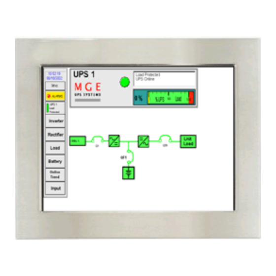
Page 40: Single-Module Ups Online
Graphical Command Center Single-Module UPS Online In normal online operation the path of power will show green from utility to unit load, as shown in Figure 4-1. Figure 4-1: S-M UPS On-Line. UPS 1 13:54:55 01/24/2003 Setu p ALARMS UPS 1... -
Page 41: Single-Module Ups On Bypass
Single-Module UPS On Bypass If there is a major fault in the UPS it will transfer to bypass. The power flow will show green from Utility 2 to the load. The section that had the fault will show red to draw attention to the fault. If the User shuts down the inverter without a major fault, then the inverter will show gray and the rectifier will show green, as shown in Figure 4-2. -
Page 42: Single-Module Ups On Battery
Single-Module UPS On Battery In battery operation the path of power will show green from the battery to unit load, and Utility 1 and Utility 2 will show red, as shown in Figure 4-3. Figure 4-3: S-M UPS on Battery. UPS 1 13:54:55... -
Page 43: S-M Battery Cb Open
Single-Module UPS Battery CB Open Battery CB open shows the battery circuit breaker QF1 in the open state. The battery and lines to the battery show red to indicate and draw attention to the fault condition, as shown in Figure 4-4. -
Page 44: Multi-Module Online
In normal online operation the path of power will show green from utility to unit load, as shown in Figure 4-5. Figure 4-5: M-M Online. 11:11:06 Setu p Trend Utility 2 ALARMS System Load Protected UPS 1 Online Utility 1 UPS 2 Online System UPS 3 Online page 4 —6 Q3BP... -
Page 45: Multi-Module 1 Ups On Battery
Multi-Module 1 UPS on Battery When a Multi-Module UPS is in battery mode the UPS icon will display in yellow. If all UPS’s that are online are in battery mode, then the line to the load will be yellow, as shown in Figure 4-6. -
Page 46: Multi-Module On Bypass
Multi-Module on Bypass If all UPS’s are faulted or offline then the system will transfer to bypass. The power flow will show green from Utility 2 to the load. UPS’s that are faulted will show red. If they are shutdown without fault then they will show gray. -
Page 47: Multi-Module Test And Maintenance Mode On Ups
Utility 2. In this condition, UPS’s can be turned on and off without affecting the customer’s load. When a UPS is online in this mode, it will show as blue instead of its normal green, as shown in Figure 4-8. -
Page 48: Multi-Module Test And Maintenance Mode On Bypass
When Q3BP and the static switch (Q2S) are closed and Q5N is open, the system is in Test and Maintenance Mode on bypass. The customer’s load is being supplied by Utility 2. In this condition, UPS’s can be turned on and off without affecting the customer’s load. -
Page 49: Multi-Module Transfer Mode
Figure 4-10. Figure 4-10: M-M Transfer Mode. 10:19:05 Setu p Trend Utility 2 ALARMS System Load Not Protected UPS 1 Offline Utility 1 UPS 2 Offline System UPS 3 Offline Q3BP UPS 1... -
Page 50: Multi-Module Communication Fault
Multi-Module Communication Fault Communication fault indicates a loss of proper communications to one or more UPS’s in the system. The fault can be caused by two problems, the unit has powered down and is no longer responding or there has been a break in the communication cable. -
Page 51: Scope
The alarm file capacity is 120 days First In - First Out (FIFO) stored in non-volatile memory. Alarms and Events List The alarms list below is for a Single-Module UPS and Static Switch Cabinet. For a Multi-Module System, the UPS module number (from 1 to 6), with the alarm will be displayed. -
Page 52: Alarm/Event Present Log Screen
Graphical Command Center The event list is for a Single-Module UPS. For a Multi-Module System, the UPS module number (from 1 to 6), with the event will be displayed. Events - UPS Modules Module 1 Low Battery Shutdown Module 1 Battery Charging... - Page 53 10/24 07:29:34 Battery CB Open 10/24 07:29:34 Rectifier/Charger Off 10/24 07:29:34 Input CB Open 10/24 07:29:34 UPS out of Sync with Bypass 10/24 07:33:28 Bypass Input Circuit Breaker Open 10/24 07:33:28 Inverter Output CB Open 10/24 07:29:34 Load Not Protected...
-
Page 54: Alarm/Event History Log Screen
Graphical Command Center Alarm/Event History Screen The Alarm/Event History screen lists all present and stored information on all alarms and events. Refer to Figure 5-2 for screen selections. Clear Log Present Alarms Active/Unack Alarms Shows how many alarms are active and unacknowledged. Year/Month/Type Filter User can filter alarms and events to be viewed as follows: calendar year, specific Up/Down Arrows Alarm/Event List... - Page 55 10/14 12:02:16 Battery CB Open 10/14 12:02:16 Rectifier/Charger Off 10/14 12:02:16 Input CB Open 10/14 12:02:16 UPS out of Sync with Bypass 10/14 12:02:16 Bypass Input Circuit Breaker Open 10/14 12:02:16 Inverter Output CB Open 10/14 12:02:16 Load Not Protected...
-
Page 56: Clear Alarm/Event Log Password Screen
Graphical Command Center Figure 5-3: Clear Alarm/Event Log Password Screen. To clear Alarm / Event Log Enter Password Password manager Enter Back to Alarms Double tap on cursor to bring up keyboard Figure 5-4: Clear Log Screen. Clear Log Back to Alarms page 5 —6 GCC Alarms... -
Page 57: Gcc Troubleshooting
To function properly, the RS232/RS485 converter needs two twisted pairs of metallic wire. These pairs must be between 19 and 26 AWG (the higher number gauges may limit distance). Figure 6-1: S-M RS485 Interface Connections with GCC. UPS 1 RAUZ1 PCBA / GTCZ COM2 1 2 3 4 5 6 7 8 9 10 1 2 3 4 5 6 7 8 9 10 4 COND. -
Page 58: Communications Port Switch Settings
1 2 3 4 5 6 7 8 9 10 4 COND. SHIELDED CABLE or DUAL TWISTED PAIR WIRE Only the end-of-line cubicle will have the “N” switch in the closed position. All other cubicles will have the “N” switch in the open position. GCC Troubleshooting UPS 1 XR11... - Page 59 Figure 6-3: “GTCZ/RAUZ1” and “GT2Z/RAUZ2” PCB Configuration Switches. SWITCHES: 4 WIRE LINK: IN A CUBICLE THAT SETS POLARITY: "RAUZ 1" OR "RAUZ 2" PCB XR11 CLOSED POSITION OPEN POSITION (two dots visible) (one dot visible) Termination for Termination for end-of-line cubicle intermediate cubicle(s) 4 WIRE LINK OTHER CUBICLE...
-
Page 60: Communications Port 2 Personalization
(Hexadecimal) - For Single-Module see section 6.4.1 - For Multi-Module see sections 6.4.2 and 6.4.3. Interface: RS485 page 6 —4 CUBICLE #2 - UPS 1 UPS 1 GTCZ / RAUZ1 COM 2 Dip Switch “O” OPEN Dip Switch “P” OPEN Dip Switch “N”... -
Page 61: Slave Address For Single-Module
6.4.1 Slave Address for Single-Module For a Single-Module UPS, the slave address settings are shown. Also see Figure 6-4. GTCZ / RAUZ1 UPS 1 COM 1 2O H COM 2 2O H Figure 6-4: S-M Slave Address Settings. GTCZ/ RAUZ1... -
Page 62: Slave Address For Multi-Module With Gcc In Each Cabinet
GTCZ / RAUZ1 COM 1 20 H COM 2 90 H GT2Z / RAUZ2 COM 1 COM 2 Figure 6-6: M-M with GCC in Each Cabinet Slave Address Settings. UPS 1 GTCZ/ GTCZ/ RAUZ1 RAUZ1 AMUZ AMUZ Comm 1 Comm 1... -
Page 63: Rs232/Rs485 Interface Converter
RS232/RS485 Interface Converter The Patton Model 2089 RS232 to RS485 interface converter requires no AC power or batteries for operation, as it is powered by the computer. 6.6.1 Switch Setting This section shows how to access the Dip switches, and describes how to set the configuration. The Model 2089 is configured using two PC board mounted 4-position Dip switches. -
Page 64: Converter Switch Access
Graphical Command Center Both Dip switches S1 and S2 are marked with individual switch numbers 1 through 4. Use these numbers, as well as the "ON" designation to orient the switch properly, see Figure 6-10. Use a small screwdriver or similar instrument to set each individual switch. -
Page 65: Auto Start
The GCC identification label is located on the rear panel of the GCC. The label is used to identify all characteristics of the GCC. It has six fields that give information on software and service pack version, UPS type, procedures (future), web pages (future), driver tracking, and application tracking. - Page 66 Graphical Command Center (This page left blank intentionally) page 6 —10...
-
Page 67: Glossary
Symbols Definition / Meaning And/or. Percentage. Plus or Minus. Number. °C Degree Celsius. °F Degree Fahrenheit. Ø Phase. ® Trade Mark. Normal sequence of phase (clockwise) in three-phase power. AC or ac Alternating current, also implies root-mean-square (rms). Alarm Warning of a fault or major status change condition. ANSI American National Standard Institute. - Page 68 Connected to the UPS output, such as computer systems or critical devices. Load protected The attached load is being supplied by the UPS module inverter output, and the battery is avail- able in the event that incoming (utility) power is lost.
- Page 69 Printed circuit board. UPS input isolation circuit breaker. Q3BP Optional maintenance bypass circuit breaker (in single-module UPS system); option- al maintenance bypass circuit breaker in MBC cabinet (shared systems). Control or bypass circuit breaker (in single-module UPS systems); user-supplied bypass AC input circuit breaker supplying the SSC (in shared systems).
- Page 70 Graphical Command Center (This page left blank intentionally) page g — 4...
-
Page 71: Index
Multi-Module on Bypass 4 —8 Multi-Module Online 4 —6 Multi-Module System Load Screen 3 —10 Multi-Module Test and Maintenance Mode on Bypass 4 —10 Multi-Module Test and Maintenance Mode on UPS 4 —9 Multi-Module Transfer Mode 4 —11 Index User Manual I n d e x page I —1... - Page 72 RS232/RS485 6 —1 RS232/RS485 Interface Converter 6 —7 RS485 Interface Connections 6 —1 Select if UPS is a 225, 300, 375 or 500KVA 2 — 2 SETUP 3 —1, 3 —2 Show CB’s/System CB Configuration 2 — 2 SINGLE-MODULE 3 —1 Single-Module Battery Screen 3 —11...
-
Page 74: Reorder Form
Use this form to order additional copies of this document, or to report any errors, omissions, or other problems you have experienced. NAME COMPANY __________________________________________________________________ STREET ADDRESS ___________________________________________________________ CITY ___________________________________ STATE ___________ ZIP ______________ I would like to order ________ (quantity @ $50.00 each) additional copies of the: Graphical Command Center I would like to report the following problems with this document: Reorder form... - Page 76 w w w . m g e u p s . c o m w w w . m g e u p s . c o m 1 6 6 0 S c e n i c Av e n u e , C o s t a M e s a , C a l i f o r n i a 9 2 6 2 6 • ( 7 1 4 ) 5 5 7 - 1 6 3 6...
Need help?
Do you have a question about the UPS and is the answer not in the manual?
Questions and answers