Table of Contents
Advertisement
Quick Links
Advertisement
Table of Contents

Subscribe to Our Youtube Channel
Related Manuals for elsner elektronik Arexa


Summary of Contents for elsner elektronik Arexa
- Page 1 Window Control Arexa Installation and Operation...
-
Page 2: Table Of Contents
Description..................... 3 Scope of supply ........................... 3 Commissioning procedure ......................... 3 Options for connection and control ....................3 Overview of available automatic functions ..................4 Operation ....................5 Key functions and display symbols of the meteorological data display ........5 Display of lightness and wind speed .................... - Page 3 View of rear side and drill hole plan for the operating unit............41 Connection samples for several drive mechanisms as group ............42 Personal setting data of the automatic...............43 Arexa • from software version operating unit 3.0, Arexa weather station 3.0 • Status: 01/10/2009. Errors excepted. Subject to technical changes.
-
Page 4: Description
Setting of the automatic (see chapter „Setting of automatic") Options for connection and control A drive mechanism for windows may be connected to the Arexa control system. If several windows shall be controlled together, the connection via a group control relay is possible. -
Page 5: Overview Of Available Automatic Functions
Arexa may be deployed in the control system XS as control centre and as transducer. In this case, the control is upgraded with motor control units and operating units of system XS. Overview of available automatic functions • Open when a selectable indoor temperature is reached •... -
Page 6: Operation
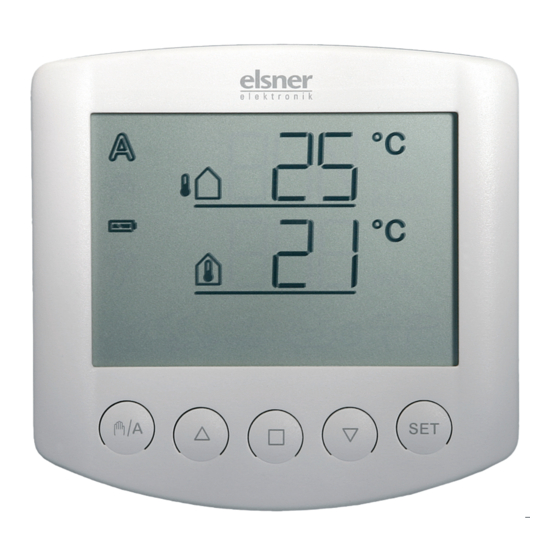
Operation Key functions and display symbols of the meteorological data display The basic position of the operating unit of the control system displays the current outdoor temperature (upper line) and the indoor temperature (lower line) as well as the function mode (automatic or manual), the battery load and the current alarm messages for rain or wind. -
Page 7: Display Of Lightness And Wind Speed
Automatic mode activated Manual mode activated. The connected drive mechanism was operated manually (with arrow keys) or key was pressed. Thus, the automatic functions are deactivated, there is no control in terms of temperature. The safety functions rain alarm and wind alarm are still activated. -
Page 8: Manual Operation
Manual operation Manual control as well as the presetting of the automatic functions and the basic setting of the connected shading is accomplished with the keys of the operating unit. Stop Down The connected window may be manually operated with the keys The arrow keys are provided with a time automatic. - Page 9 In order to get to the display, press key twice shortly in automatic mode ( and once shortly in manual mode ( As long as the display shows , manual operating commands of this operating unit are submitted to all drive mechanisms in system XS. During this display, use the keys in order to centrally operate all drive mechanisms.
-
Page 10: Setting Of Automatic
Setting of automatic For an optimal aeration, the values for automatic operation must be adjusted to the local conditions. The following settings are queried one after the other: A. Indoor temperature for opening B. Outdoor temperature block C. Wind alarm D. -
Page 11: Indoor Temperature For Opening
You may leave the automatic settings at any time by pressing the key . The accomplished changes of the values are not saved in this case. If you do not press any key in the automatic settings for 5 minutes, the display automatically changes to temperature display. -
Page 12: Outdoor Temperature Block
B. Outdoor temperature block After the setting of the indoor temperature, now select the maximum outdoor temperature up to which the window shall remain closed. The outdoor temperature block keeps the window closed as long as the temperature is below the selected value. This means that in automatic mode, an opened window is closed and not opened again if the indoor temperature value (chapter A) is exceeded. - Page 13 The wind alarm protects the window and furniture and fixtures from damage. If the indicated wind value is exceeded, the window closes and the manual operation is blocked. Wind speed is indicated in m/sec (meters per second). The wind alarm is maintained for 5 minutes.
-
Page 14: Rain Alarm
D. Rain alarm After the setting of the wind alarm, now select whether the rain alarm shall be switched on or off. The rain alarm protects furniture and fixtures from damage. In case of rain, the window is automatically retracted and the manual operation is blocked. The rain message is maintained for 5 minutes. -
Page 15: Basic Settings
Basic settings These are the basic settings of the device for the commissioning of the control system. The following settings are queried one after the other: 1. Radio connection to the weather station 2. Rotational direction of the motor 3. Operating direction 4. - Page 16 You may leave the basic settings at any time by pressing the key . The accomplished changes are not saved in this case. If you do not press any key in the basic settings for 5 minutes, the display automatically changes to temperature display. Accomplished settings are not saved either.
-
Page 17: Radio Connection To The Weather Station
1. Radio connection to the weather station The first step is the teaching in (or later the deletion) of the radio connection. The teaching in may only be accomplished by a qualified person for electronics because the programming key is inside the weather station. -
Page 18: Rotational Direction Of The Motor
2. Rotational direction of the motor After the teaching in of the radio, you may now set the rotational direction of the motor. If the up and down connection cables have been mixed up when connecting the drive mechanism, this may be corrected in this step. First open the window a little bit for the rotational direction test. -
Page 19: Operating Direction
3. Operating direction After the setting of the rotational direction of the motor, now select which key shall open the window. In this step, you change the allocation of the arrow keys so that they correspond with the operating direction of the window. You may directly test the setting with the arrow keys. -
Page 20: Operating Command In Case Of Wind Or Rain Alarm
4 minutes or is permanently maintained as long as the alarm message exists. The permanent operating command is necessary if Arexa is used as control centre for wired motor drive units (e. g. IMSG 230) which control several drive mechanisms. -
Page 21: Sending Of Meteorological And Automatic Data
After the setting of the operating command in case of wind or rain alarm, you may now select, whether the meteorological data and the automatic commands of Arexa shall be submitted by radio to the motor control units of system XS. Leave this display at if Arexa is used as conventional single-channel control system. -
Page 22: Opening Position
6. Opening position After the setting of the sending of meteorological and automatic data, you may now teach in an opening position. You may determine an individual position for the window up to which it opens in automatic mode. Select the desired step with the key: (continue) in order to skip the setting of the opening position. -
Page 23: Closed Position
6.1. Closed position After having confirmed (learn), the command (close) appears. At first, completely close the window. Then press the key in order to access the next setting step. 6.2. Setting of the desired position The command (open) appears. Now open the window as far as the automatic shall do it later. Then press the key in order to access the next setting step. -
Page 24: Saving Of Basic Settings
7. Saving of basic settings At the end of basic settings, the symbol (save) asks whether the accomplished setting shall be saved. Press the key in order to save your entered data and to access the meteorological data display. With , you quit the basic settings without saving. - Page 25 If cleaning and maintenance works in the environment of the awing(s) or blind(s) must be accomplished, the control system (weather station) must be switched to neutral by switching off the installed fuse and be prevented from unintentional restart. Thus you ensure that the connected drive mechanisms do not start operation.
-
Page 26: Installation And Commissioning
The control must only be operated as stationary system, i.e. only in a fitted state and after completion of all installation and start-up works, and only in the environment intended for this purpose. Elsner Elektronik does not assume any liability for changes in standards after publication of this instruction manual. -
Page 27: Installation Of Weather Station And Connection Of Drive Mechanism
Installation of weather station and connection of drive mechanism Position Select an assembly site at the building where wind, rain and sun may be collected by the sensors unobstructedly. Do not assemble any construction components above the weather station from where water may drop on to the rain sensor after it has stopped raining or snowing. - Page 28 When pole mounting: curved side on pole, collar downward. An additional, optional accessory available from Elsner Elektronik is an articulated arm for flexible wall, pole or beam mounting of the weather station. Examples for the application of the hinge arm mounting: Ex.1: With the hinge arm mounting, the...
-
Page 29: Preparation Of The Weather Station
Preparation of the weather station The cover of the weather station with rain sensor is engaged at the lower rim to the right and to the left (see fig.) Remove the cover from the weather station. Be careful not to break away the cable connection between the circuit board in the bottom part and the rain sensor in the cover. -
Page 30: Connection Of Voltage Supply And Drive Mechanism
Cable connection to the rain sensor in the housing cover Connections for the drive mechanism (tension clamp, PE/N/up/down), suitable for solid conductors up to 1.5 mm² or conductors with fine wires Opening for the cable for the drive mechanism Connections for voltage supply (230 V AC, tension clamp, L1/N/PE), suitable for massive conductors of up to 1.5 mm²... -
Page 31: Mounting Of The Weather Station
Check whether cover bottom correctly engaged! The figure illustrates the closed weather station from below. Mounting of the weather station Push the housing into the mounted holder from above. The journals of the holder must engage with the rails of the housing. If you want to remove the weather station, you must pull it out of the holder in upwards direction against the resistance of the engagement. -
Page 32: Installation Of Operating Unit
Installation of operating unit The operating unit is battery-powered and communicates with the weather station per radio. When you select the assembly site, please avoid direct sun because this would distort the measurements of the indoor temperature. The appropriate sensor is integrated in the lower part of the operating unit. - Page 33 • Insert batteries in the operating unit as described in chapter “Insert batteries”. • The display of the operating unit now indicates that the radio connection between weather station and operating unit is not taught in. • Press key for 3 seconds until the following display appears: •...
-
Page 34: Sensor Testing
• Then check the function of the sensors (see next chapter). Sensor testing In case of malfunctions of the sensors, the display shows error messages instead of values. Please observe the chapter „Error messages“ on this. Sun sensor testing By the short pressing of the key on the operating unit you get to the lightness display (see chapter "Display of lightness and wind speed"). -
Page 35: Service
Service Service and maintenance Weather station The weather station must regularly be checked for dirt twice a year and cleaned if necessary. In case of severe dirt, the wind sensor may not work properly anymore, there might be a permanent rain message or the station may not identify the sun anymore. -
Page 36: Error Messages
Observe the correct polarity of the batteries. You need two standard batteries (1.5 V) or accumulators (1.2 V) of type AA (Mignon/ LR6). Close the housing by fitting the front panel with circuit board from above into the rear panel. The locking must engage with a clearly noticeable "click". Error messages Despite the values for temperature, lightness or wind speed, the display may indicate error messages in the meteorological data display. - Page 37 Cause: No radio connection between operating unit and weather station. The weather station is out of order (e.g. has no voltage) or the radio connection is interrupted or has not yet been taught in. Action: The error may only be corrected by a qualified person for electronics.
-
Page 38: Query Service Data
10 means version 1.0, 12 means 1.2, etc. Quit the service data display by another short pressing of Factory settings The following presetting for the automatic is stored when the Arexa control system is delivered: • Opening from indoor temperature > 25°C •... -
Page 39: Operating Unit
The product has been tested for the above mentioned standards by an accredited EMV laboratory. Operating unit Operating voltage 2 x 1.5 V (2 batteries, AA/Mignon/LR6) or 2 x 1.2 V (2 accumulators, AA/Mignon/ LR6) Ambient temperature storage -10°C to +50°C Ambient temperature operation 0°C to +50°C Air humidity... -
Page 40: Connection Diagram For Weather Station
Connection diagram for weather station The operating unit is battery-powered. The communication between operating unit and weather station is accomplished by radio. -
Page 41: View Of Rear Side And Drill Hole Plan For The Weather Station
View of rear side and drill hole plan for the weather station All values are in mm, deviations due to technical reasons are possible. -
Page 42: View Of Rear Side And Drill Hole Plan For The Operating Unit
View of rear side and drill hole plan for the operating unit All values are in mm, deviations due to technical reasons are possible. -
Page 43: Connection Samples For Several Drive Mechanisms As Group
Connection samples for several drive mechanisms as group... -
Page 44: Personal Setting Data Of The Automatic
Personal setting data of the automatic Opening if indoor temperature exceeds °C Outdoor temperature block below °C Wind alarm from m/sec Rain alarm (Yes/No) - Page 45 Elsner Elektronik GmbH Steuerungs- und Automatisierungstechnik Herdweg 7 D-75391 Gechingen Germany Phone: +49 (0) 70 56/93 97-0 Fax: +49 (0) 70 56/93 97-20 info@elsner-elektronik.de http://www.elsner-elektronik.de...
Need help?
Do you have a question about the Arexa and is the answer not in the manual?
Questions and answers