Table of Contents
Advertisement
Quick Links
Advertisement
Table of Contents

Related Manuals for TMT TI-2300

Summary of Contents for TMT TI-2300
- Page 1 TI-2300 / 3000 VER 101 WIDE INDICATOR USER’S MANUAL www.tmteng.com...
-
Page 2: Table Of Contents
INDEX 1. Introduction ................3 2. Main Features ................3 3. Technical Specifications ............4 4. Description of Panels and Symbols ......... 6 5. Installation ................... 7 6. General Function ..............10 7. Test Mode ................. 11 8. Setting Mode ................13 9. -
Page 3: Introduction
◆ Do not connect incompatible adaptor. Use only adaptor approved by TMT for use with this particular model. The use of any other types may invalidate any approval or warranty, and may be dangerous. For availability of approved enhancements, please check with your dealer. -
Page 4: Technical Specifications
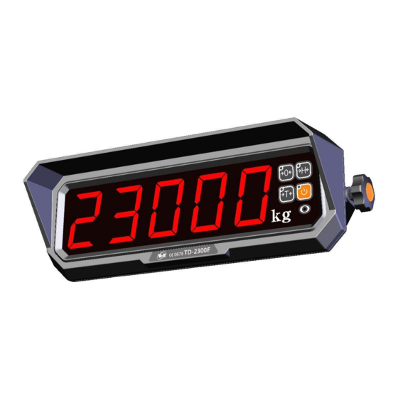
3. Technical Specifications ◆ Specifications Display TI-2300: 2.3inch 5 FND / TI-3000: 3inch 5 FND Display lamp Zero, Tare, Hold, Stable, Power Touch key Zero, Tare, Hold, On/Off Case material Engineering plastic Load Cell Excitation DC 5V, 300mA (up to 8 load cell) Input sensitivity 0.2uV/D... - Page 5 ◆ Dimensions 1) TI-2300 2) TI-3000...
-
Page 6: Description Of Panels And Symbols
4. Description of Panels and Symbols ◆ Display Displays weight or messages STABLE Indicates that the weight to be in stable condition ZERO Indicates that scale is stable and at zero TARE Indicates that scale is currently using a tare HOLD Indicates that the HOLD feature has been activated ◆... -
Page 7: Installation
5. Installation Power adaptor + (RED) Power adaptor – (BLACK) Extra RS232C TXD Extra RS232C RXD Extra RS232C GND... - Page 8 Not used RS232C TXD (OP-01) RS232C RXD (OP-01) RS232C GND (OP-01) SIG+ SIG- POWER ZERO TARE External key 4 contact / 4inputs (OP-01) HOLD EVCC+ OUT1 2 solid state relays contact (OP-01) EVCC+ OUT2...
- Page 9 1) External input circuit ※ External inputs are interlocked with the touch keys. 2) Solid state relay circuit ※ EVCC+ range: DC12~28V range: > 2KΩ ※ R load ※ Output conditions Output Conditions Low limit< Measured value ≤ High limit OUT2 ON (low limit) OUT1 ON (high limit) High limit <...
-
Page 10: General Function
6. General Function (1) Zero Function Use to correct drifted zero value when the scale is unloaded, and motion is not detected. This function works when ZERO KEY is pressed, and the ZERO LAMP is on. (2) Setting Tare Weight Function Press the TARE KEY. -
Page 11: Test Mode
7. Test Mode (1) How to enter this mode Press the ON KEY to power on and immediately press ZERO KEY to enter test mode. (2) Testing Menu (TEST 1 – TEST4) ■ TEST 1 : Keyboard Test Remote Display Description Control ZERO... - Page 12 ■ TEST 4 : Solid state relay output test Display Description ZERO KEY: All outputs are turned off. OUT-0 HOLD KEY: Increase the output number & this output is turned on. If press the TARE KEY, move on weighing mode.
-
Page 13: Setting Mode
8. Setting Mode (1) How to enter this mode Press the ON KEY to power on and immediately press TARE KEY to enter setting mode. (2) Keyboard ■ ZERO KEY : Use to set up an initial zero value (0). (F4,F18,F19: Used to move the input value to the left or right by one place) ■... - Page 14 F04 : Assignment of Automatic zero calibration (0~99) Settings Meaning F4-00 Automatic zero calibration is not carried out. Automatic zero is calibrated for change under 1 gradation F4-23 for 3 sec. Automatic zero is calibrated for change under 4.5 gradation F4-99 for 9 sec.
- Page 15 F09 : Function * key of remote controller (0~2) Settings Meaning F09-0 Operation is equal to the * key of the master F09-1 Send data command key (Print format) F09-2 Send data command key (18bytes format) F10 : Hold key function (0,1) Settings Meaning F10-0...
- Page 16 [FORM 0] [FORM 1] 2013.10.13 12:00 2013.10.13 12:00 001, ID_9, 25 kg SN_02, ID_9, 25 kg F14 : : Initialization of serial number (0,1) Settings Meaning F14-0 Maintain current number F14-1 Initialization (starting from No.1) F15 : Auto transmit at stable (0~2) Settings Meaning F15-0...
- Page 17 F18 : Setting low limit (not included weighing points) Settings Meaning 20.0kg (In case of one decimal point) Select a digit place to be inputted with ZERO KEY. Input a figure with HOLD KEY. Press TARE KEY to enter the value. F19 : Setting high limit (not included weighing points) Settings Meaning...
-
Page 18: Calibration
9. Calibration Press the ON KEY to power on and immediately press HOLDE KEY until ‘-----’ is displayed and press ZERO KEY. And then ‘G-CAL’ is displayed and press TARE KEY to enter calibration mode. Title Display Operation & Description ☞... -
Page 19: Infrared Remote Controller
10. Infrared Remote Controller (1) How to use ■ OFF KEY : Use to power on/off the TI series ■ ZERO KEY : Same as keyboard of TI series ■ TARE KEY : Same as keyboard of TI series ■ HOLD KEY : Same as keyboard of TI series ■... -
Page 20: Wireless Specifications
11. Wireless Specifications RF frequency range 2400 ~ 2483.5 MHz Output power Max. 4dBm Channel width 2 MHz Frequency offset < ±30ppm Transmit data rate 250Kbps,500Kbps Receiver sensitivity -99dBm (PER <1%) Maximum input level 0dBm RF In/out impedance 50 ohm (TXRF, RXRF) Spurious(2nd harmonics) <... -
Page 21: Rs232C Format
12. RS232C Format 1) Type : EIA-RS-232C 2) Method : Full-duplex, asynchronous transmission Format ① Baud rate : 9600 bps ② Data bit: 8, Stop bit: 1, Parity bit: None ③ Code : ASCII 3) Format (18byte) Lamp Start Code Blank Weighing data Unit... -
Page 22: Real Time Clock
13. Real Time Clock (1) How to enter this mode Press the ON KEY to power on and immediately press HOLD KEY. And press the TARE KEY again. (2) Keyboard : Used to increase the setting constant one by one. : Used to move the input value to the left or right by one place. -
Page 23: Check Message
14. Check Message Data in an internal storage allocation are erased owing to any electronic impact. ☞ Please contact us to resolve this technical problem. Something wrong in a Load cell connection or in an serial connection. ☞ Please contact us to resolve this technical problem. Load cell output is too small (large) at SPAN calibration. - Page 24 MEMO...
Need help?
Do you have a question about the TI-2300 and is the answer not in the manual?
Questions and answers