Table of Contents
Advertisement
Quick Links
COMMUNICATIONS-APPLIED TECHNOLOGY
11250-14 Roger Bacon Drive
Reston, VA 20190
USA
Voice: 800-229-3925/+1-703-481-0068
Support: Techsupport@c-at.com
April 2015
Rev B
SETUP and OPERATING MANUAL
ADVANCED MULTI-CHANNEL VEHICLE INTERCOM
SYSTEM (AMCVIS)
with
DIGITAL CREW CONTROL
The AMCVIS was designed, manufactured and is supported by:
COMMUNICATIONS-APPLIED TECHNOLOGY CO.
RESTON, VA, USA
http://www.c-at.com
If you have any questions, please contact:
C-AT TECHNICAL SUPPORT at 800-229-3925/+1-703-481-0068 (voice), 703-471-4428 (fax), or
E-mail to
techsupport@c-at.com
Advertisement
Table of Contents

Subscribe to Our Youtube Channel
Summary of Contents for COMMUNICATIONS-APPLIED TECHNOLOGY AMCVIS
- Page 1 SETUP and OPERATING MANUAL ADVANCED MULTI-CHANNEL VEHICLE INTERCOM SYSTEM (AMCVIS) with DIGITAL CREW CONTROL The AMCVIS was designed, manufactured and is supported by: COMMUNICATIONS-APPLIED TECHNOLOGY CO. RESTON, VA, USA http://www.c-at.com If you have any questions, please contact: C-AT TECHNICAL SUPPORT at 800-229-3925/+1-703-481-0068 (voice), 703-471-4428 (fax), or E-mail to techsupport@c-at.com...
-
Page 2: Table Of Contents
TABLE OF CONTENTS DIGITAL AMCVIS SYSTEM ..........................2 FIGURE 1: DIGITAL AMCVIS SYSTEM CONFIGURATION ..............2 THEORY OF OPERATION ...........................3 SYSTEM COMPONENTS ..........................4 1.1. INTERCOM MASTER UNIT (IMU): ...................... 4 FIGURE 2: INTERCOM MASTER UNIT (IMU) FRONT PANEL ..............4 FIGURE 3: REAR and SIDE of INTERCOM MASTER UNIT (IMU) ............4 1.2. -
Page 3: Digital Amcvis System
DIGITAL AMCVIS SYSTEM FIGURE 1: DIGITAL AMCVIS SYSTEM CONFIGURATION - 2 -... -
Page 4: Theory Of Operation
THEORY OF OPERATION The AMCVIS-D (p/n 500.7045) provides up to five personnel with a two way intercom capability. All headset station ports have common capabilities. The AMCVIS-D provides the five users with the ability to simultaneously monitor two, 2-way radios---connected to the AMCVIS---and to transmit on one of them. -
Page 5: System Components
1.1. INTERCOM MASTER UNIT (IMU): The IMU is the AMCVIS system controller. It contains the various audio circuits, power supply, two radio interfaces and five intercom station interfaces. The components are housed in a splash-proof, rugged metal housing that can be mounted in a wheeled vehicle or boat. -
Page 6: Intercom Control Unit (Icu)
RADIO P-T-T button (these transmissions are also heard by all intercom users). All AMCVIS users (intercom and radio) hear all voice communications. All five users can be talking on the intercom or radio at the same time. -
Page 7: Amcvis Adjustments Prior To Operation
2. AMCVIS ADJUSTMENTS PRIOR TO OPERATION 2.1. CONNECTING IMU COMPONENTS: Securely connect power cable into the IMU power jack. When the power switch is in the “ON” position, the Red LED on the right side of the IMU will be lit. - Page 8 To Radio #2 Set for undistorted audio from a headset to radio #2. Set with headset microphone place close to speaker’s lips. Radio # 2 must be selected at the ICU and the Radio P-T-T must be depressed and held. From Radio #2 Set for maximum undistorted audio at a headset from radio #2.
-
Page 9: Imu Controls And Indicators
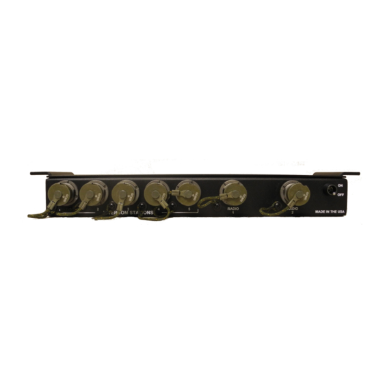
3. IMU CONTROLS AND INDICATORS 3.1. FRONT PANEL FIGURE 6: IMU FRONT PANEL POWER “On/Off” Switch: This is a two position switch is used to turn the IMU power “ON” and “OFF INTERCOM STATION Jacks 1-5: Pin A: Mic High Pin B: PCB Ground Pin C: Audio out to headset Pin D: Control signal... - Page 10 SIDE and REAR PANEL FIGURE 7: IMU SIDE/REAR PANELS POWER LED (Red): When this LED is lit, it indicates that the IMU is enabled RADIO #1 P-T-T LED (Green): When this LED is lit, it indicates that Radio #1 is being keyed at an ICU. RADIO #2 P-T-T LED (Green): When this LED is lit, it indicates that Radio #2 is being keyed at an ICU.
-
Page 11: Icu Controls And Indicators
4. ICU CONTROLS AND INDICATORS On the ICU is a jack that will mate with U-174/U headset plug. A spring-loaded clothing clip is provided on the ICU. To plug the cable’s connector into a jack on the front of the IMU, align the ICU plug and IMU jack Intercom and Radio P-T-T switches, and volume control are installed on the ICU. -
Page 12: Cable And Connector Instructions
5. CABLE AND CONNECTOR INSTRUCTIONS 5.1. POWER CABLE: The IMU power cable is supplied with an unterminated end. The cable should be secured away from any sharp objects. Power requirement for the IMU is +11 to +24 volts DC from vehicle or an external power source. -
Page 13: Radio Cable
5.2. RADIO CABLE: The IMU radio cables should be routed to their associated radios. The cables should be secured away from any sharp objects. To plug the cable’s connector into the IMU, take off the dust cover by turning counterclockwise. Align the connector keyway (red dot) and push the connector into the receptacle turning clockwise until it “locks”... -
Page 14: Appendix A: System Components
APPENDIX A: SYSTEM COMPONENTS Component Part Number Quantity required Intercom Master Unit (IMU) 500.7045 1 each Power supply interconnect cable 500.0757-10 1 each stripped and tinned SINCGARS, MBITR, “green gear” radio interface cable with 179.0615 2 each ENVIRONMENTAL connector on both ends Intercom Control Unit (ICU) Specially 1 each per user,... -
Page 15: Appendix B: System Preventative Maintenance
APPENDIX B: SYSTEM PREVENTATIVE MAINTENANCE Before each use please check the following: 1. Make sure all connectors are dry tight and clean. A pencil eraser and a can of compressed air can be used to brighten contacts and remove dust and debris. -
Page 16: Appendix C: Aluminum Mounting Brackets Template
APPENDIX C: ALUMINUM MOUNTING BRACKETS TEMPLATE Note: SEE FULL SIZE TEMPLATE ATTACHED (DWG#087-1098-8) (P/N: 500.7045) DIMENSIONS SHOWN IN INCHES FIGURE 12: MOUNTING BRACKET TEMPLATE - 15 -...
Need help?
Do you have a question about the AMCVIS and is the answer not in the manual?
Questions and answers