Advertisement
Table of Contents
- 1 Table of Contents
- 2 Warning Labels
- 3 Electrical Power Supply
- 4 Control Panel
- 5 Electrical Components
- 6 Parts
- 7 Cabinet & Panels
- 8 Base
- 9 Pressure and Exhaust System
- 10 Control Panel
- 11 Heating Elements and Insulation
- 12 Cooking Well
- 13 Lower Control Box
- 14 Meat Rack
- 15 Tiered Food Basket
- Download this manual
SERVICE & PARTS MANUAL
®
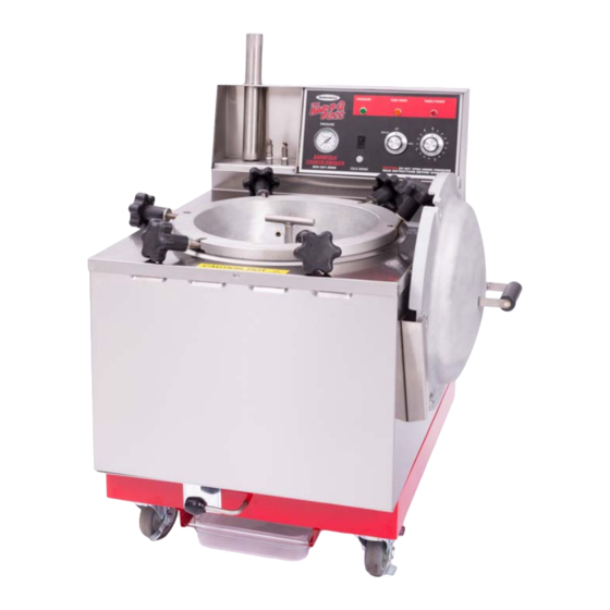
Bar-B-Q Boss
Pressure Smoker
Models BC71 and BC73
Be sure ALL installers read, understand, and have access to this manual at all times.
Smokaroma® is a registered trademark.
Broaster Company
2855 Cranston Road, Beloit, WI 53511-3991
608/365-0193 broaster.com
Design Certified By:
© 2017 Broaster Company
Manual #17897 7/17
UL, CUL & NSF
Printed In U.S.A.
Advertisement
Table of Contents

Related Manuals for Smokaroma Bar-B-Q Boss

Summary of Contents for Smokaroma Bar-B-Q Boss
- Page 1 Bar-B-Q Boss Pressure Smoker Models BC71 and BC73 Be sure ALL installers read, understand, and have access to this manual at all times. Smokaroma® is a registered trademark. Broaster Company 2855 Cranston Road, Beloit, WI 53511-3991 608/365-0193 broaster.com Design Certified By: ©...
- Page 3 Indicates a potentially hazardous situation which, if not avoided, could result in minor injury, property damage or both. All adjustments and repairs shall be made Rags or paper containing by an authorized Smokaroma representa- cooking oil can catch fire tive. if exposed to heat. Laundering will not remove the oil.
-
Page 5: Table Of Contents
TABLE OF CONTENTS 1. Warning Labels ..................1 - 1 2. ELECTRICAL POWER SUPPLY ................... 2 - 1 WIRING DIAGRAM 1 PHASE .................. 2 - 2 WIRING DIAGRAM 3 PHASE .................. 2 - 3 3. CONTROL PANEL ......................3 - 1 4. -
Page 7: Warning Labels
1 - WARNING LABELS broaster.com Manual #17897 7/17... -
Page 9: Electrical Power Supply
2 - ELECTRIC POWER SUPPLY ELECTRICAL SAFETY ACCESS FOR SERVICE Many parts of this section For access to the electrical compartment, pertain to checking and re- remove rear cover. pairing electrical components. High Voltage will be encountered in several instances. Only persons trained and equipped for checking high voltage shall undertake such repairs. - Page 10 208V, 220V & 240V 1ph: broaster.com Manual #17897 7/17...
- Page 11 208V, 220V & 240V 3ph: broaster.com Manual #17897 7/17...
-
Page 13: Control Panel
3 - CONTROL PANEL PRESSURE GAUGE: Indicates the pres- THERMOSTAT: Puts the smoker in either sure present in the Cooking Well. BAR-B-Q or HOLD mode. When set, pro- vides power to the power relay/contactor to PRESSURE - GREEN LIGHT: Illuminates the heating elements. - Page 14 ACCESS FOR SERVICE 1. Unplug power cord. 2. Remove rear cover of unit. broaster.com Manual #17897 7/17...
- Page 15 PRESSURE GAUGE COLD SMOKE SWITCH 1. See ACCESS FOR SERVICE. 2. Disconnect the hose from the fitting on the back of the pressure gauge. 3. Remove the (2) mounting nuts and the mounting clamp from the gauge. 4. Pull gauge out of control panel from 1.
- Page 16 LIGHTS Terminals 5 & 6 are jum- pered together and should be toward the right end when facing the back of the control panel. 3. Transfer the wires from one ter- minal to the same terminal on the new terminal block. Method 2 1.
-
Page 17: Electrical Components
4 - ELECTRICAL COMPONENTS Many of the components 4. Remove timer mounting screws from in this section will have front holding the timer in place. wires that will need to be connected to the terminal (TB) the diagram below 5. Remove timer from panel and discon- shows how the terminals are numbered. - Page 18 THERMOSTAT: 13. Lay unit on its back. Removal & Installation: 14. Insert bulb under clamp on bottom of cooking well and tighten screw enough to hold bulb in place. Tightening screw too much may damage the bulb. 15. Set unit upright on its casters. 16.
- Page 19 PRESSURE SWITCHES: 7. Reconnect wires as indicated in the di- agram at left. REPLACEMENT: 8. Adjust pressure switch PS1 as de- scribed in the PRESSURE SWITCH ADJUSTMENT section. 9. Reinstall rear panel. 10. Plug in power cord to put unit back in service.
- Page 20 clockwise to re-energize the power re- PRESSURE SWITCH ADJUST- lay/contactor. As the pressure passed MENT 12 PSI adjust the knurled nut counter- clockwise to de-energize the power re- lay/contactor. Test to ensure that the power relay/contactor continues to de- energize at 12 PSI. 1.
- Page 21 CONTACTORS & RELAYS: THREE PHASE SINGLE PHASE 1. Unplug power cord. 2. Remove rear panel of unit. 1. Unplug power cord. 3. Disconnect all wires from the contac- 2. Remove rear panel of unit. tor. 3. Disconnect all wires from the relay, Make note of where each making note of where each wire is con- wire is connected.
- Page 22 SOLENOID VALVE CHARRING ELEMENT: 1. Unplug power cord. 2. Remove rear panel of unit. 3. Disconnect the black solenoid valve wires from PS2 and TB-5. 4. Disconnect fittings A & B as shown in the diagram below. 1. Unplug power cord. 2.
- Page 23 HEATING ELEMENTS: 6. Remove the front and side panels 7. Remove the insulation band clamp. Replacement of the heat- ing elements should not 8. Carefully remove the insulation and set be done on site because of time and it aside. space needed to do the replacement.
- Page 24 21. Turn the unit over onto it’s casters. 22. Reconnect the heating element jump- ers as shown below or on next page per voltage specified on specification plate. broaster.com Manual #17897 7/17...
-
Page 25: Parts
5 - PARTS All adjustments and repairs shall be made by an authorized Broaster Company representative. CABINET & PANELS 001549 broaster.com Manual #17897 7/17... -
Page 26: Base
BASE PARTS broaster.com Manual #17897 7/17... -
Page 27: Pressure And Exhaust System
PRESSURE AND EXHAUST SYSTEM PARTS 001568 001568 broaster.com Manual #17897 3/18... -
Page 28: Control Panel
CONTROL PANEL PARTS broaster.com Manual #17897 7/17... -
Page 29: Heating Elements And Insulation
HEATING ELEMENTS AND INSULATION PARTS broaster.com Manual #17897 7/17... -
Page 30: Cooking Well
COOKING WELL PARTS broaster.com Manual #17897 7/17... -
Page 31: Lower Control Box
LOWER CONTROL BOX PARTS broaster.com Manual #17897 3/18... - Page 32 COVER PARTS broaster.com Manual #17897 7/17...
-
Page 33: Meat Rack
MEAT RACK broaster.com Manual #17897 7/17... -
Page 34: Tiered Food Basket
TIERED FOOD BASKET 5-10 broaster.com Manual #17897 7/17... - Page 35 SERVICE NOTES...
- Page 36 SERVICE NOTES...
- Page 37 SERVICE NOTES...
- Page 40 Broaster Company 2855 Cranston Road, Beloit, WI 53511-3991 608/365-0193 broaster.com...
Need help?
Do you have a question about the Bar-B-Q Boss and is the answer not in the manual?
Questions and answers