Table of Contents
Advertisement
Quick Links
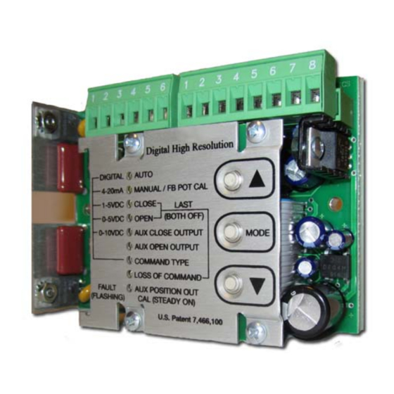
Flomatic Smart Card
Model FDHC-100 (Digital High-Resolution Controller)
Configuration and Operation Manual
The Flomatic FDHC-100 is a high performance
Digital positioner intended to control AC actuators,
providing 450 points of resolution with quarter turn
actuators ranging from 2 sec to 120 sec and rated for
25% duty or more. The FDHC-100 has many automatic
advanced features that will enhance any actuator while
making it easy to install and set up.
The simple three button control is used to configure all
parameters the unit needs for a wide variety of
applications, and allows the
to be easily set for direct or reversing acting without
any rewiring. The unit can be configured for various
command types (4-20mA, 1-5V, 0-5V, 0-10V, or a
digital command) and its default operation upon loss of
command.
Various option modules are easily plugged into the unit,
providing other features such as a position feedback
signal (current or voltage), auxiliary switches, fault relay
contact, or digital communications. A wide range of data is accessible through a digital communications
module, providing additional control or information.
The unit is of single solid construction and is easily mounted with two screws. The FDHC-100 is
interchangeable with the AMC and LRC standard size controllers, and can be used to upgrade
performance for those applications.
FEATURES
•
Positions to ±0.1° with quarter-turn actuators ranging from 2 sec to 120 sec (with or without a
brake).
•
Adaptive Control feature continuously adjusts for load and actuator conditions and eliminates
calibration procedures and auto-cal operations.
•
Three button control provides easy setup and eliminates the need for instrumentation.
•
Polarity Detection feature allows direct or reverse acting operation without re-wiring.
•
Electronic Brake feature can eliminate need for a mechanical brake in many applications, and
extends mechanical brake life when used.
•
Stall Detection feature protects actuator motor from a stall condition.
•
Automatic Duty Cycle Control feature prevents shutdown of a process due to a thermal overload of
the actuator motor, and allows actuators rated for 25% duty or more to be safely used.
•
Operating temperature range of 0 to 60°C
Flomatic Corporation
Glens Falls, NY 12801
Phone (518) 761-9797
Fax (518) 761-9798
TM
open
closed
and
positions
FDHC-100 Configuration & Operation Man. Rev 0
August 16, 2010
DHC-100 / DHC-100C 117VAC (CE ready)
DHC-100A / DHC-100D 234VAC
DHC-100B / DHC-100D 24VAC (CE ready)
1 of 14
Advertisement
Table of Contents

Related Manuals for Flomatic FDHC-100


Summary of Contents for Flomatic FDHC-100
- Page 1 A wide range of data is accessible through a digital communications module, providing additional control or information. The unit is of single solid construction and is easily mounted with two screws. The FDHC-100 is interchangeable with the AMC and LRC standard size controllers, and can be used to upgrade performance for those applications.
- Page 2 Configuration and Operation Manual OUTLINE FDHC-100 / FDHC-100C 117VAC (CE ready) FDHC-100A / FDHC-100D 234VAC FDHC-100B / FDHC-100E 24VAC (CE ready) FDHC-100 Configuration & Operation Man. Rev 0 Flomatic Corporation August 16, 2010 Glens Falls, NY 12801 2 of 14...
-
Page 3: Block Diagram
BLOCK DIAGRAM DESCRIPTION The FDHC-100 is rated for motors with up to 5A running currents and comes in three versions to accommodate different voltage applications. The FDHC-100 and FDHC-100C are rated for 117 VAC ±10%; the FDHC-100A and FDHC-100D are rated for 234 VAC ±10%, and the FDHC-100B and FDHC- 100E are rated for 24 VAC ±10%. - Page 4 Motor Neutral wire must be connected to pin 2, while one motor winding is connected to pin 1 and the other winding to pin 3. The feedback potentiometer wiper must be connected to pin 5, while one end is connected to pin 4 and the other end to pin 6. The Polarity Detection feature of the FDHC-100 open...
-
Page 5: Override Mode
The 15 minute period can also be terminated using the OFF or STOP function. The motor is also automatically turned off if the FDHC-100 detects a stall (see STALL DETECTION). An OPEN or CLOSE operation can be attempted again after switching to the OFF, LATCH, or STOP functions first. - Page 6 AUTO The AUTO function is the normal mode of operation for the FDHC-100; all the other functions are used to set up the unit. While in AUTO, the unit can be controlled by various external signals, some of which can be selected by the COMMAND INPUT function.
-
Page 7: Command Type
Aux Close position, the Aux Close Output indicator will flash. Additionally, the FDHC-100 will turn on a relay output on the optional relay module - the output can be used to drive an alarm or merely act as an auxiliary limit switch. Upon selecting the AUX CLOSE OUTPUT function, the FDHC-100 will begin moving the actuator to the previously set position. -
Page 8: Fault Indicator
The fault condition will disable the Motor 1 output only, and the fault is cleared when the FDHC-100 detects a motion greater than 1.5° in either direction. The fault can be cleared if 1) the command signal commands a Motor 2 operation, 2) manual operation with the adjust buttons results FDHC-100 Configuration &... - Page 9 DUTY CYCLE CONTROL FEATURE The Duty Cycle Control feature of the FDHC-100 allows actuators rated at 25% duty or more to be safely used in automated valve applications. The FDHC-100 accurately monitors the relative heating of the motor and automatically duty cycles the unit at a safe level when a process becomes unstable, or if a control loop is not properly set.
-
Page 10: Option Modules
While this operation slows down the actuator’s operation, it does not impact the resolution performance of the FDHC-100, and it prevents disruption of a process due to a thermal switch shutdown. -
Page 11: Specifications
132 MHz to 142 MHz can increase immunity by installing a clamp-on ferrite (250 ohms or more at 100MHz) around the I/O cable(s). A Steward 28A2029-0A2 ferrite or equivalent is recommended. FDHC-100 Configuration & Operation Man. Rev 0 Flomatic Corporation... -
Page 12: Wiring Diagrams
Flomatic Smart Card Model FDHC-100 (Digital High-Resolution Controller) Configuration and Operation Manual WIRING DIAGRAMS Input Signal Configurations FDHC-100 Configuration & Operation Man. Rev 0 Flomatic Corporation August 16, 2010 Glens Falls, NY 12801 12 of 14 Phone (518) 761-9797 Fax (518) 761-9798... - Page 13 Flomatic Smart Card Model FDHC-100 (Digital High-Resolution Controller) Configuration and Operation Manual WIRING DIAGRAMS Special Applications FDHC-100 Configuration & Operation Man. Rev 0 Flomatic Corporation August 16, 2010 Glens Falls, NY 12801 13 of 14 Phone (518) 761-9797 Fax (518) 761-9798...
- Page 14 Flomatic Smart Card Model FDHC-100 (Digital High-Resolution Controller) Configuration and Operation Manual WIRING DIAGRAMS Special Applications (continued) FDHC-100 Configuration & Operation Man. Rev 0 Flomatic Corporation August 16, 2010 Glens Falls, NY 12801 14 of 14 Phone (518) 761-9797 Fax (518) 761-9798...