Table of Contents

Subscribe to Our Youtube Channel
Related Manuals for Cinterion MTX-65i-RS485LC

Summary of Contents for Cinterion MTX-65i-RS485LC
- Page 1 MTX-65i-RS485 LC GSM-GPRS terminal modem http://www.mtx-terminals.com MTX-65i-RS485LC TERMINAL User Manual Powered by Cinterion WM TC65i GSM-GPRS Wireless Module MTX-65i-RS485 User Manual V.1.0 Pag. 1 Subject to change without prior notice...
- Page 2 MTX-65i-RS485 LC GSM-GPRS terminal modem http://www.mtx-terminals.com General Notes Product is deemed accepted by recipient and is provided without interface to recipient’s products. The documentation and/or product are provided for testing, evaluation, integration and information purposes. The documentation and/or product are provided on an “as is”...
- Page 3 MTX-65i-RS485 LC GSM-GPRS terminal modem http://www.mtx-terminals.com REVISION INFORMATION FIRST EDITION. VERSION 1.0. Release: Apr 2013 MTX-65i-RS485 User Manual V.1.0 Pag. 3 Subject to change without prior notice...
-
Page 4: Table Of Contents
MTX-65i-RS485 LC GSM-GPRS terminal modem http://www.mtx-terminals.com 1. INTRODUCTION ..............................6 1.1 Description ..........................6 1.2 ORDERING INFORMATION ...................... 6 1.3 Highlights ..........................7 1.4 MTX-65i-RS485-LC Wireless modems in a Communication System ..........9 1.5 Main Features and Services ..................... 9 1.5.1 Types of Mobile Station .......................... - Page 5 MTX-65i-RS485 LC GSM-GPRS terminal modem http://www.mtx-terminals.com 7.3.1 General ............................... 33 7.3.2 Antenna type ............................... 33 7.3.3 Antenna placement ............................. 33 7.3.4 The antenna cable ............................33 7.3.5 Possible communications disturbances ...................... 34 8. ACCESSORIES ..............................35 8.1. POWER SUPPLY ........................35 8.1.1 AC Power Adaptor .............................
-
Page 6: Introduction
With quad band 900/1800 MHz and 850/1900 MHz, your applications can be used all over the world. The MTX-65i-RS485-LC incorporates a Cinterion WM TC65i module. Note! Some of the functions described inside this Technical Description are only possible when the SIM- Card is inserted 1.2 ORDERING INFORMATION... -
Page 7: Highlights
MTX-65i-RS485 LC GSM-GPRS terminal modem http://www.mtx-terminals.com 1.3 Highlights Interfaces • GSM FME M antenna connector • GPS SMA F antenna connector 2 Analog Input 1 x I2C/SPI bus. SPI optional. 1 x 4-wires RS232 UART flow control RS485 port USB 2.0 port •... - Page 8 MTX-65i-RS485 LC GSM-GPRS terminal modem http://www.mtx-terminals.com Short Message Service (SMS) Features • Point-to-point MO and MT • SMS cell broadcast • Text and PDU mode Internet Protocols TCP/UDP/IP protocol stack Extensive AT command access to TCP/IP stack Internet Services: TCP, UDP, HTTP, FTP, SMTP, POP3 Open application resources ARM©...
-
Page 9: Mtx-65I-Rs485-Lc Wireless Modems In A Communication System
MTX-65i-RS485 LC GSM-GPRS terminal modem http://www.mtx-terminals.com 1.4 MTX-65i-RS485-LC Wireless modems in a Communication System Figure 1 and Figure 2 illustrate the main blocks of a wireless communication system using the wireless modem. Figure 1 shows the communication system when a micro-controller is used. They also show the communication principles of the system and the interface between the wireless modem and the application and Figure 2 shows the communication system when the JAVA application is embedded on the wireless modem. -
Page 10: Short Message Service
MTX-65i-RS485 LC GSM-GPRS terminal modem http://www.mtx-terminals.com Feature GSM850 E-GSM900 GSM1800 GSM1900 824-849 880-915 1710-1785 1850-1910 Frequency range (MHz) 869-894 925-960 1805-1880 1930-1990 RF power @ARP with 33dBm 33dBm 30dBm 30dBm 50 load (typ) Channel spacing 200kHz 200kHz 200kHz 200kHz Number of channels Number of TD slots Duplex spacing 45MHz... -
Page 11: Gprs Multi-Slot Support
MTX-65i-RS485 LC GSM-GPRS terminal modem http://www.mtx-terminals.com 1.5.4 GPRS Multi-Slot Support GSM Multi-slot classes supported by MTX-65i-RS485-LC Multi-slot Maximum slot allocation Allowable Configuration Max data rate Class Downlink Uplink Active 1 up; 4 down 8-12Kbps Send 32-48Kbps Receive 1 up; 4 down 8-12Kbps Send 32-48Kbps Receive 2 up;... - Page 12 MTX-65i-RS485 LC GSM-GPRS terminal modem http://www.mtx-terminals.com Average power consumption Parameter Description Conditions Unit VPOWER Operating Voltage for one minute POWER Power Down mode 0.45 Average supply current (average time 3 min.) @12V 0.50 @25°C @ worst case: GSM 900 max power level @30V 0.80...
-
Page 13: Sim Card
Do not exceed the environmental and electrical limits as specified in Technical Data 1.7 Block diagram GSM Antenna FME M connector interface Mini Terminal External block power Cinterion TC65i R1 6-28VDC GSM/GPRS Power Wireless module ASC1 ASC0 Serial Port RS485 pins RS232 Level... -
Page 14: Mechanical Description
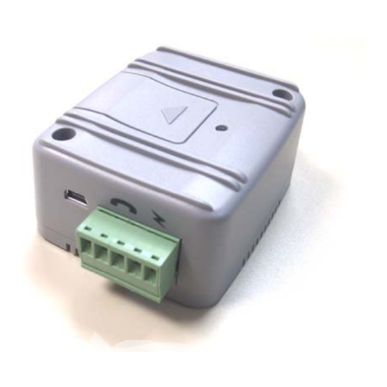
MTX-65i-RS485 LC GSM-GPRS terminal modem http://www.mtx-terminals.com 2. MECHANICAL DESCRIPTION 2.1 Overview The pictures below show the mechanical design of the module along with the positions of the different connectors and mounting holes. The module case is made of durable PC/ABS plastic. 2.2. -
Page 15: Electrical Description
MTX-65i-RS485 LC GSM-GPRS terminal modem http://www.mtx-terminals.com 3. ELECTRICAL DESCRIPTION All electrical connections to the module are protected in compliance with the standard air and contact Electrostatic Discharge (ESD). The module uses the following industry standard connectors: High density 15 pin D-Sub (Main RS232 UART and extended I/O interface) 5 pin terminal block for DC powering and RS485 BUS SIM card reader FME male coaxial jack (GSM antenna connector) -
Page 16: Mini Usb Connector
MTX-65i-RS485 LC GSM-GPRS terminal modem http://www.mtx-terminals.com 3.2 Mini USB Connector The USB 2.0 interface allows connectivity to all relevant PCs and control boards in office and industrial environments. The USB interface is a USB 2.0 full speed (12Mbit/s) interface for AT-C modem functionality between the MTX-65i-RS485-LC Terminal and e.g. -
Page 17: Sim Card Reader
MTX-65i-RS485 LC GSM-GPRS terminal modem http://www.mtx-terminals.com 3.4. SIM card reader The MTX-65i-RS485-LC+G terminal is fitted with a SIM card reader designed for 1.8V and 3V SIM cards. It is the flip-up type which is lockable in the horizontal position and is accessed through a removable panel as shown below. -
Page 18: Main Serial Rs232 Interface Port
MTX-65i-RS485 LC GSM-GPRS terminal modem http://www.mtx-terminals.com 3.6 MAIN Serial RS232 Interface Port ASC0 The modem supports a standard RS232 serial interface (EIA/TIA 574) via its 15 pin Sub-D connector, shown below. It is connected to TC65i ASC0 port using a level shifter converter. Pin Signal RD 0 TD 0... - Page 19 MTX-65i-RS485 LC GSM-GPRS terminal modem http://www.mtx-terminals.com • By default it is configured in fixed rate 115200 bauds. • Autobauding is not compatible with multiplex mode. Autobauding is NOT recommended when using SDK debug and MES applications. Please use fixed baud rate, as 115200 8N1. •...
-
Page 20: Rs485 Bus
MTX-65i-RS485 LC GSM-GPRS terminal modem http://www.mtx-terminals.com 3.7. RS485 BUS The RS485 BUS is connected to TC65i ASC1 port using level shifter converter. It meets or exceeds the requirements of ANSI TIA/EIA-485-A PIN: Signal Limits Description -RxB RS485 +RxA RS485 NOT CONNECTED. Reserved for AUTO ON Input 0 –... -
Page 21: I2C Serial Control Bus
MTX-65i-RS485 LC GSM-GPRS terminal modem http://www.mtx-terminals.com 3.7.2. I2C Serial Control Bus I2C is a serial, 8-bit oriented data transfer bus for bit rates up to 400kbps in Fast mode. It consists of two lines, the serial data line I2CDAT and the serial clock line I2CCLK. The MTX-65i-RS485-LC module acts as a single master device, e.g. -
Page 22: Spi Bus
MTX-65i-RS485 LC GSM-GPRS terminal modem http://www.mtx-terminals.com 3.7.3. SPI Bus The SPI (serial peripheral interface) is a synchronous serial interface for control and data transfer between the MTX-65i-RS485-LC Terminal and the connected application. Only one application can be connected to the module’s SPI. The interface supports transmission rates up to 6.5Mbit/s. It consists of four lines, the two data lines SPIDI/SPIDO, the clock line SPICLK and the chip select line SPICS. -
Page 23: Analog-To-Digital Converter
MTX-65i-RS485 LC GSM-GPRS terminal modem http://www.mtx-terminals.com Signal name Description SPICS NOT ENABLED. By default is RTS. Can be changed to: SPICS: Chip select – selects and activates the external device via a low signal. SPIDI NOT ENABLED. By default is CTS. Can be changed to: SPIDI: Data in –... -
Page 24: Operation
MTX-65i-RS485 LC GSM-GPRS terminal modem http://www.mtx-terminals.com 4. OPERATION 4.1 Switching On the Modem. New “Automatic Restart after shutdown” feature There is no special way to turn the modem on. Just apply power in VCC (pin 4) and GND (Pin 5). The modem is fully operational after 4 seconds. - Page 25 MTX-65i-RS485 LC GSM-GPRS terminal modem http://www.mtx-terminals.com 75 ms on / 75 ms off / One or more GPRS PDP contexts activated. Same as for AT^SSYNC=1 75 ms on / 3 s off 500 ms on / 50 ms off Packet switched data transfer is in progress Same as for AT^SSYNC=1 Depending on type of call: Voice call: Connected to remote party.
-
Page 26: Embedded Applications
MTX-65i-RS485 LC GSM-GPRS terminal modem http://www.mtx-terminals.com 5. EMBEDDED APPLICATIONS. The MTX-65i-RS485-LC can embed an internal application written in popular JAVA language. Java technology and several peripheral interfaces on the module allow you to easily integrate your application. This way the customer application can be reduced because all of the resources (Microcontroller, Flash & RAM memory), all kinds of I/Os and bus peripherals can be used by the customer. -
Page 27: Mtx-Tunnel Software Application
JAVA code which fits into 99% of M2M applications: MTX-TUNNEL. This is optional and must be ordered separately. MTX-TUNNEL is an application running in the GSM-GPRS Terminals and is based on the Cinterion TC65i which is designed for communicating with remote devices that have RS232/I2C- SPI ports. It is a frequently the... - Page 28 MTX-65i-RS485 LC GSM-GPRS terminal modem http://www.mtx-terminals.com MTX-TUNNEL FEATURES GPRS-SERIAL TUNNEL TCP Client TCP Server UDP Client / Server GPRS connection modes: Permanent mode Under request (SMS or missed call, authorized or not phone numbers) Change on an input digital level An analog input is out of selected level window (MIN, MAX) Serial data present on RS232/RS485 port Scheduled date/hour timing...
-
Page 29: Safety And Product Care
MTX-65i-RS485 LC GSM-GPRS terminal modem http://www.mtx-terminals.com 6 SAFETY AND PRODUCT CARE Please read the information in this section and the information in “Installation of the Modem”, before starting your integration work! 6.1. Safety instructions PLEASE READ THESE SAFETY INSTRUCTIONS AND KEEP A COPY OF THEM. •... -
Page 30: Sim Card Precautions
MTX-65i-RS485 LC GSM-GPRS terminal modem http://www.mtx-terminals.com 6.3. SIM card precautions Before handling the SIM card in your application, ensure that you are not charged with static electricity. Use proper precautions to avoid electrostatic discharges. • When the SIM card hatch is opened, the SIM card connectors lie exposed under the SIM card holder. Caution! Do not touch these connectors! If you do, you may release an electrical discharge that could damage the modem or the SIM card. -
Page 31: Personal Medical Devices
MTX-65i-RS485 LC GSM-GPRS terminal modem http://www.mtx-terminals.com 6.6. Personal Medical Devices Wireless modem devices may affect the operation of cardiac pacemakers, hearing aids and certain other implanted equipment. If a minimum distance of 15 cm (6 inches) is maintained between the MTX-65i- RS485-LC terminal radiating antenna and a pacemaker, the risk of interference is limited. -
Page 32: Installation Of The Modem
MTX-65i-RS485 LC GSM-GPRS terminal modem http://www.mtx-terminals.com 7. INSTALLATION OF THE MODEM This chapter gives you advice and helpful hints on how to integrate the MTX-65i-RS485-LC Terminal into your application from a hardware perspective. 7.1 Where to install the modem There are several conditions which need to be taken into consideration when designing your application as they might affect the modem and its function. -
Page 33: Securing The Modem
MTX-65i-RS485 LC GSM-GPRS terminal modem http://www.mtx-terminals.com 7.2.2 Securing the modem Before securing the modem take into account the amount of additional space required for the mating connectors and cables that will be used in the application. • Where access is restricted, it may be easier to connect all the cables to the modem prior to securing it in the application. -
Page 34: Possible Communications Disturbances
MTX-65i-RS485 LC GSM-GPRS terminal modem http://www.mtx-terminals.com 7.3.5 Possible communications disturbances Possible communication disturbances include the following: • Noise can be caused by electronic devices and radio transmitters. • Path-loss occurs as the strength of the received signal steadily decreases in proportion to the distance from the transmitter. -
Page 35: Accessories
MTX-65i-RS485 LC GSM-GPRS terminal modem http://www.mtx-terminals.com 8. ACCESSORIES The MTX-65i-RS485-LC has been type approved together with a range of accessories including: Power supply, all type of antennas (indoor, outdoor, high gain, etc…), cables and DIN adapters The following are examples of these. Please visit www.mtx-terminals.com to see the full-range of accessories. -
Page 36: Antennas
MTX-65i-RS485 LC GSM-GPRS terminal modem http://www.mtx-terminals.com 8.2. ANTENNAS 8.2.1 GSM Magnetic Dual Band Antenna (900/1800MHz) OPANIEL TECHNOLOGIES http://www.opaniel.com Model: MTX-FME F (whips 6 & 22 cm) Magnetic-mount antenna, 3m RG174 cable with FME female connector 0dB radiator for whip 6 cm. 3dB radiator for whip 22 cm. -
Page 37: Cables
MTX-65i-RS485 LC GSM-GPRS terminal modem http://www.mtx-terminals.com 8.3. CABLES 8.3.1 Main port - RS232 4-way Serial Cable Modem and System Breakout Cable: 1m lead length • HD15 male connector Connected to; • DB9 female connector with 4 signal RS232 serial connection 11 flying leads ( 7 opened ) Conductor current rating <... -
Page 38: Usb Cable
MTX-65i-RS485 LC GSM-GPRS terminal modem http://www.mtx-terminals.com 8.3.2 USB CABLE Cable USB 2.0 AM/Mini BM (5 pins) Black Length 1.8 meters Ordering Code: 120.003.222 8.3.3 Adapter DB15 F – DB9 M ORDER CODE: 118.001.007 8.4. DIN Mounting Kit ORDER CODE: 118.001.010 Screws for Terminals TORNILLO PLANO DIN84 M3x35 for all MTX-Terminals models. -
Page 39: 9, Conformity Assessment
28019 Madrid Spain We declare under our sole responsibility that the products, MTX-65i-RS485-LC Terminal 0 containing Cellular Engine Cinterion engine TC65i (Type L30960-N-1150-*), to which this declaration relates are labelled with the CE conformity mark. STANDARDS of EUROPEAN TYPE APPROVAL... -
Page 40: Fcc Compliant And Sar Information
Notes: Quad band GSM/GPRS Modem The MTX-65i-RS485-LC-V3 contains FCC ID: QIPTC65I Cinterion Wireless Modules model TC65i is marketed without defined antenna. Maximum Gain antennas using indoor antennas depend on distance from the antenna to any nearby persons. Normally, it should not exceed the values shown on the table below. -
Page 41: Rohs Statement
MTX-65i-RS485 LC GSM-GPRS terminal modem http://www.mtx-terminals.com 10. ROHS STATEMENT The MTX-65i-RS485-LC terminal is compliant with the 2002/95/EC Directive of the European Parliament and of the Council of 27 January 2003 on the restriction of the use of certain hazardous substances in electrical and electronic equipment (RoHS). -
Page 42: Abbreviations
MTX-65i-RS485 LC GSM-GPRS terminal modem http://www.mtx-terminals.com 12. ABBREVIATIONS Abbreviation Explanations Cell Broadcast Message Cell Broadcast Service Circuit Switched Data Data Circuit Terminating Equipment Data Terminal Equipment DTMF Dual Tone Multi Frequency Enhanced Full Rate Electro-Magnetic Compatibility ETSI European Telecommunication Standards Institute Full Rate GPRS General Packet Radio Service... -
Page 43: At Command Summary
MTX-65i-RS485 LC GSM-GPRS terminal modem http://www.mtx-terminals.com 13. AT COMMAND SUMMARY The AT standard is a line-oriented command language. AT is an abbreviation of ATtention and it is always used to start sending a command line from the terminal equipment (TE) to the terminal adaptor (TA). The command line consists of a string of alphanumeric characters. - Page 44 MTX-65i-RS485 LC GSM-GPRS terminal modem http://www.mtx-terminals.com AT+CGDCONT Define PDP Context AT+CGEQMIN 3G Quality of Service Profile (Minimum acceptable) AT+CGEQREQ 3G Quality of Service Profile (Requested) AT+CGMI Request manufacturer identification AT+CGMM Request model identification AT+CGMR Request revision identification of software status AT+CGPADDR Show PDP address AT+CGQMIN...
- Page 45 MTX-65i-RS485 LC GSM-GPRS terminal modem http://www.mtx-terminals.com AT+CNUM Read own numbers AT+COLP Connected Line Identification Presentation AT+COPN Read operator names AT+COPS Operator Selection AT+CPAS Mobile equipment activity status AT+CPBR Read from Phonebook AT+CPBS Select phonebook memory storage AT+CPBW Write into Phonebook AT+CPIN PIN Authentication AT+CPIN2...
- Page 46 MTX-65i-RS485 LC GSM-GPRS terminal modem http://www.mtx-terminals.com AT+FTH Transmit Data Using HDLC Framing AT+FTM Transmit Data AT+FTS Stop Transmission and Wait AT+GCAP Request complete TA capabilities list AT+GMI Request manufacturer identification AT+GMM Request model identification AT+GMR Request revision identification of software status AT+GSN Request International Mobile Equipment Identity (IMEI) AT+ICF...
- Page 47 MTX-65i-RS485 LC GSM-GPRS terminal modem http://www.mtx-terminals.com AT^SCPOL Polling Configuration AT^SCPORT Port Configuration AT^SCSL Customer SIM Lock AT^SCTM Set critical operating temperature presentation mode or query temperature AT^SDLD Delete the 'last number redial' memory AT^SDPORT Delete a Port Configuration AT^SFDL Enter Firmware Download Mode AT^SFNUR Select the fixed network user rate AT^SGACT...
- Page 48 MTX-65i-RS485 LC GSM-GPRS terminal modem http://www.mtx-terminals.com AT^SLCC Siemens defined command to list current calls of ME AT^SLCD Display Last Call Duration AT^SLCK Facility lock AT^SLMS List SMS Memory Storage AT^SM20 Set M20 compatibility mode AT^SMGL List Short Messages from preferred store without setting status to REC READ AT^SMGO Set or query SMS overflow presentation mode or query SMS overflow AT^SMGR...
- Page 49 MTX-65i-RS485 LC GSM-GPRS terminal modem http://www.mtx-terminals.com AT^SRSA Remote SIM Access Activation AT^SRSM Remote SIM Access Message AT^SRTC Ring tone configuration AT^SSCNT Start and Stop Pulse Counter AT^SSCONF SMS Command Configuration AT^SSDA Set SMS Display Availability AT^SSET Indicate SIM data ready AT^SSIO Set IO state of a specified pin or port AT^SSMSS...
- Page 50 MTX-65i-RS485 LC GSM-GPRS terminal modem http://www.mtx-terminals.com Select pulse dialling Set result code presentation mode ATS0 Set number of rings before automatically answering a call ATS0 Automatic response to a network request for PDP context activation ATS10 Set disconnect delay after indicating the absence of data carrier ATS18 Extended call release report ATS3...
-
Page 51: Sales Contact
MTX-65i-RS485 LC GSM-GPRS terminal modem http://www.mtx-terminals.com 15. SALES CONTACT Documentation Manuals Drivers ftp.matrix.es/MTX-Terminals DEVELOPMENT KITS Cinterion SDK gsmsupport@matrix.es for FTP access & details. www.mtx-terminals.com gsmsupport@matrix.es Matrix Madrid Matrix Electronica S.L.U. C/ Alejandro Sánchez, 109 28019 - Madrid Spain Tel. +34 91 5602737 Fax.
Need help?
Do you have a question about the MTX-65i-RS485LC and is the answer not in the manual?
Questions and answers