Table of Contents
Advertisement
Advertisement
Table of Contents

Related Manuals for Cinterion MC55i

Summary of Contents for Cinterion MC55i
- Page 1 MC55i Terminal Version: 01.201a DocId: MC55i_Terminal_HD_v01.201a...
- Page 2 UCT") IS SUBJECT TO THE RELEASE NOTE PROVIDED TOGETHER WITH PRODUCT. IN ANY EVENT THE PROVISIONS OF THE RELEASE NOTE SHALL PREVAIL. THIS DOCUMENT CON- TAINS INFORMATION ON CINTERION PRODUCTS. THE SPECIFICATIONS IN THIS DOCUMENT ARE SUBJECT TO CHANGE AT CINTERION'S DISCRETION. CINTERION WIRELESS MODULES GMBH GRANTS A NON-EXCLUSIVE RIGHT TO USE THE PRODUCT.
-
Page 3: Table Of Contents
Overview ......................18 Block Diagram....................19 Operating Modes ..................... 20 Terminal Circuit....................21 Power Supply....................22 3.5.1 Turn MC55i Terminal on ..............23 3.5.2 Reset MC55i Terminal ................ 23 3.5.3 Turn MC55i Terminal off ..............23 3.5.4 Disconnecting power supply ............... 24 3.5.5... - Page 4 MC55i Terminal Hardware Interface Description Contents Mechanical Characteristics..................42 Mounting Example ................... 43 Full Type Approval....................44 Cinterion Reference Setup................44 Restrictions ...................... 45 CE Conformity....................45 EMC ......................... 45 Compliance with FCC Rules and Regulations ..........46 List of Parts and Accessories.................. 47 MC55i_Terminal_HD_v01.201a...
- Page 5 Table 13: Absolute maximum ratings................33 Table 14: Operating supply voltage for MC55i Terminal..........33 Table 15: Ambient operating temperature of MC55i Terminal according to IEC 60068-2 (w/o forced air circulation)............34 Table 16: Storage conditions ..................35 Table 17: On/Off control line specifications (requirements) ...........
- Page 6 SIM interface ....................29 Figure 9: Status LED ...................... 30 Figure 10: Antenna interface .................... 31 Figure 11: Antenna connector circuit on MC55i module ..........31 Figure 12: Recommended antenna connector ..............32 Figure 13: Mechanical dimensions................... 42 Figure 14: Recommended screws..................
-
Page 7: Document History
Preceding document: "MC55i Terminal Hardware Interface Description" Version 01.201 New document: "MC55i Terminal Hardware Interface Description" Version 01.201a Chapter What is new Added remark on MC55i Terminal being the successor of the MC35i Terminal. 1.3.1 Revised directives and standards. Added temperature and weight information. -
Page 8: Introduction
MC55i Terminal. It specifies standards pertaining to wireless applications and outlines requirements that must be adhered to for successful product design. The MC55i Ter- minal is a compact GSM modem for the transfer of data, voice, SMS and faxes in GSM net- works. -
Page 9: Terms And Abbreviations
MC55i Terminal Hardware Interface Description 1.2 Terms and Abbreviations Terms and Abbreviations Table 1: Terms and abbreviations Abbreviation Description Analog-to-Digital Converter Antenna Reference Point ASIC Application Specific Integrated Circuit AT Cellular Base Transceiver Station Cell Broadcast CODEC Coder-Decoder Central Processing Unit... - Page 10 MC55i Terminal Hardware Interface Description 1.2 Terms and Abbreviations Table 1: Terms and abbreviations Abbreviation Description Low voltage Directive Mbps Mbits per second Machine Machine Interface Mobile Originated Mobile Station Mobile Terminated Not Connected Negative Temperature Coefficient Power Amplifier...
-
Page 11: Regulatory And Type Approval Information
Regulatory and Type Approval Information 1.3.1 Directives and Standards MC55i Terminal has been designed to comply with the directives and standards listed below. Table 2: Directives 99/05/EC Directive of the European Parliament and of the council of 9 March 1999 on radio equipment and telecommunications terminal equipment and the mutual recognition of their conformity (in short referred to as R&TTE Direc-... -
Page 12: Table 5: Requirements Of Quality
MC55i Terminal Hardware Interface Description 1.3 Regulatory and Type Approval Information Table 4: Standards of European type approval ETSI EN 301 489-1 Candidate Harmonized European Standard (Telecommunications series) V1.8.1 Electro Magnetic Compatibility and Radio spectrum Matters (ERM); Elec- tro Magnetic Compatibility (EMC) standard for radio equipment and ser- vices;... -
Page 13: Table 7: Toxic Or Hazardous Substances Or Elements With Defined Concentration Limits
MC55i Terminal Hardware Interface Description 1.3 Regulatory and Type Approval Information Table 7: Toxic or hazardous substances or elements with defined concentration limits MC55i_Terminal_HD_v01.201a Page 13 of 47 2010-04-16 Confidential / Released... -
Page 14: Safety Precautions
The following safety precautions must be observed during all phases of the operation, usage, service or repair of any cellular terminal or mobile incorporating MC55i Terminal. Manufactur- ers of the cellular terminal are advised to convey the following safety information to users and operating personnel and incorporate these guidelines into all manuals supplied with the prod- uct. - Page 15 MC55i Terminal Hardware Interface Description 1.3 Regulatory and Type Approval Information IMPORTANT! Cellular terminals or mobiles operate using radio signals and cellular networks. In that case connections cannot be guaranteed at all times under all conditions. There- fore, you should never rely solely upon any wireless device for essential communi- cations, for example emergency calls.
-
Page 16: Product Concept
Key Features at a Glance Feature Implementation General Incorporates MC55i The MC55i module handles all processing for audio, signal and data within module the MC55i Terminal. Internal software runs the application interface and the whole GSM protocol stack. Frequency bands... - Page 17 Enhanced full rate EFR (ETS 06.50/06.60/06.80) • Adaptive Multi Rate AMR Echo cancellation, DTMF, 7 ringing tones Software AT commands Hayes 3GPP TS 27.007, TS 27.005, Cinterion Firmware update Upgradeable via serial interface. Interfaces Serial interface • RS-232 interface, bi-directional bus for AT commands and data.
-
Page 18: Interface Description
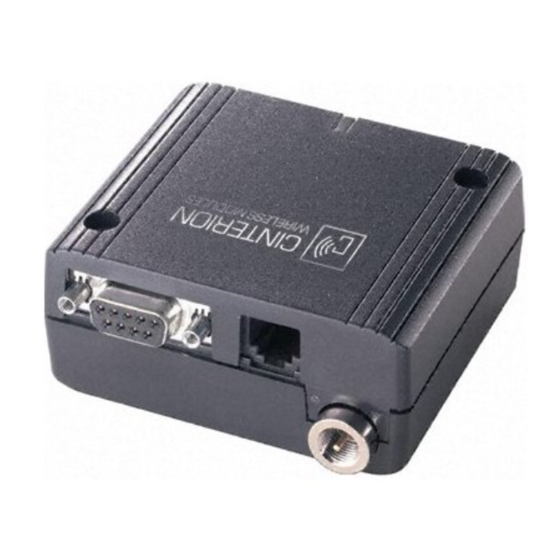
MC55i Terminal Hardware Interface Description 3 Interface Description Interface Description Overview MC55i Terminal provides the following connectors for power supply, interface and antenna: • 6-pole Western plug (female) for power supply, ignition, power down signal • 4-pole Western plug (female) for audio accessory, such as a handset •... -
Page 19: Block Diagram
MC55i Terminal Hardware Interface Description 3.2 Block Diagram Block Diagram Figure 2 shows a block diagram of a sample configuration that incorporates an MC55i Terminal and typical accessories. Antenna reference point (ARP) Antenna interface Antenna RS-232 interface Host Data... -
Page 20: Operating Modes
MC55i Terminal Hardware Interface Description 3.3 Operating Modes Operating Modes The table below briefly summarizes the various operating modes referred to in the following chapters. Table 8: Overview of operating modes Normal operation GSM / GPRS SLEEP Various power save modes set with AT+CFUN com- mand. -
Page 21: Terminal Circuit
Fuse Voltage VDDLP limiter Power supply (Power down supply) Terminal circuit Antenna Interface RF cable U.FL-R-SMT (Antenna reference point) Antenna interface FME 50 Ohm Figure 3: MC55i Terminal circuit block diagram MC55i_Terminal_HD_v01.201a Page 21 of 47 2010-04-16 Confidential / Released... -
Page 22: Power Supply
MC55i Terminal Hardware Interface Description 3.5 Power Supply Power Supply The power supply of the MC55i Terminal has to be a single voltage source of V =8V…30V PLUS capable of providing a peak current (pulsed 2x577ms at T=4.615ms) of about 1.2A at 12V dur- ing an active transmission. -
Page 23: Turn Mc55I Terminal On
The IGT_IN signal is activated when an appropriate power sup- ply unit is plugged to the 6-pole Western jack. While the PD_IN pin (pin3) is not active (voltage <2V) you can start the MC55i Terminal by ac- tivating the RS-232 DTR line. -
Page 24: Disconnecting Power Supply
3.5.6 The internal Real Time Clock (RTC) of the MC55i Terminal retains the time and date and han- dles the alarm (reminder) function. The AT+CCLK command serves to set the time and date, and AT+CALA specifies a reminder message. See for details. -
Page 25: Rs-232 Interface
Unsolicited Result Code (URC) is received. There are different modes of opera- tion, which can be set with AT commands. Note: The /DTR signal will only be polled once per second from the internal firmware of MC55i. MC55i_Terminal_HD_v01.201a... -
Page 26: Audio Interface
MC55i Terminal Hardware Interface Description 3.7 Audio Interface Audio Interface The audio interface provides an analog input for a microphone and an analog output for an ear- piece. • The microphone input and the earpiece output are balanced. •... -
Page 27: Supported Audio Modes
1. The settings are optimized for the reference handset (type Votronic) connected to the MC55i Terminal. To ensure that the reference parameters are always within the limits de- manded by the standards they cannot be changed by AT command. Furthermore, the refer- ence parameters are set as factory default. -
Page 28: Speech Processing
MC55i Terminal Hardware Interface Description 3.7 Audio Interface 3.7.2 Speech processing The voiceband filter includes a digital interpolation low-pass filter for received voiceband sig- nals with digital noise shaping and a digital decimation low-pass filter for voiceband signals to be transmitted. -
Page 29: Sim Interface
Removing and inserting the SIM card during operation requires the software to be reinitialized. Therefore, after reinserting the SIM card it is necessary to restart MC55i Terminal. Note: No guarantee can be given, nor any liability accepted, if loss of data is encountered after removing the SIM card during operation. -
Page 30: Status Led
A green LED displays the operating status of the terminal: Figure 9: Status LED The LED is driven by the SYNC line of the integrated MC55i module which can be configured by using the AT^SSYNC command. For the purpose of the MC55i Terminal it is recommended to retain the default setting of AT^SSYNC=1 (AT^SSYNC=0 is not applicable). -
Page 31: Antenna Interface
MC55i Terminal withstands a total mismatch at this connector when transmitting with power control level for maximum RF power. Inside the MC55i module a 27nH inductor to ground provides additional ESD protection to the antenna connector. For details see Figure 11. -
Page 32: Figure 12: Recommended Antenna Connector
MC55i Terminal Hardware Interface Description 3.10 Antenna Interface For the application it is recommended to use an antenna with the following FME (female) con- nector: Figure 12: Recommended antenna connector Please note that the terminal should be installed and operated with a minimum distance of 20cm between the antenna connected to the terminal and any human bodies. -
Page 33: Electrical And Environmental Characteristics
Mechanical vibrations @ 5-200Hz amplitude Mechanical pulse-acceler- @ 18 ms duration ation max. 3.0V while MC55i Terminal is switched on. Table 14: Operating supply voltage for MC55i Terminal Parameter Unit Supply voltage PLUS mea- 7.6 lowest voltage sured at (6-pole) western (minimum peak) incl. -
Page 34: Operating Temperatures
MC55i Terminal Hardware Interface Description 4.2 Operating Temperatures Operating Temperatures Table 15: Ambient operating temperature of MC55i Terminal according to IEC 60068-2 (w/o forced air circulation) Parameter Unit Normal operation °C Restricted operation -20 to -30 +65 to +75 °C... -
Page 35: Storage Conditions
MC55i Terminal Hardware Interface Description 4.3 Storage Conditions Storage Conditions Table 16: Storage conditions Type Condition Unit Reference Air temperature: °C ETS 300 019-2-1: T1.2, IEC 60068-2-1 Ab High ETS 300 019-2-1: T1.2, IEC 60068-2-2 Bb Humidity relative: High 90 at 30°C... -
Page 36: Electrical Specifications Of The Application Interface
MC55i Terminal Hardware Interface Description 4.4 Electrical Specifications of the Application Interface Electrical Specifications of the Application Interface 4.4.1 On/Off Control Table 17: On/Off control line specifications (requirements) Parameter Description Conditions Min. Max. Unit Input voltage active high high... -
Page 37: Rs-232 Interface
MC55i Terminal Hardware Interface Description 4.4 Electrical Specifications of the Application Interface 4.4.2 RS-232 Interface Table 18: RS-232 interface specifications (requirements) Parameter Description Conditions Min. Max. Unit Transmitter output volt- @ 3kOhm load ±5 ±6 ±7 age for /RXD, /CTS, /DSR, /... -
Page 38: Audio Interface
MC55i Terminal Hardware Interface Description 4.4 Electrical Specifications of the Application Interface 4.4.3 Audio Interface Table 19: Audio interface specifications (requirements) Parameter Min. Typ. Max. Unit Microphone DC (no load) at MICP MICP, MICN DC at MICP in POWER DOWN... -
Page 39: Electrical Characteristics Of The Voiceband Part
MC55i Terminal Hardware Interface Description 4.5 Electrical Characteristics of the Voiceband Part Electrical Characteristics of the Voiceband Part The electrical characteristics of the voiceband part depend on the current audio mode selected by the AT command AT^SNFS. See Table 11: Audio modes. -
Page 40: Power Supply Ratings
MC55i Terminal Hardware Interface Description 4.6 Power Supply Ratings Power Supply Ratings Table 21: Power supply specifications (to be defined) Parameter Description Conditions Min. Typ Max. Unit Allowed voltage ripple (peak- TALK mode, power control PLUS peak), drop during transmit... -
Page 41: Antenna Interface
MC55i Terminal Hardware Interface Description 4.7 Antenna Interface Antenna Interface Table 22: Antenna interface characteristics Parameter Unit Frequency range GSM 850 Uplink (MS BTS) E-GSM 900 GSM 1800 1710 1785 GSM 1900 1850 1910 Frequency range GSM 850 Downlink (BTS ... -
Page 42: Mechanical Characteristics
Restricted operation: -30°C to -20°C and +65°C to +75°C Protection class IP40 (Avoid exposing MC55i Terminal to liquid or moisture, for exam- ple do not use it in a shower or bath.) Mechanical vibrations Amplitude 7.5 mm at 5-200 Hz sinus Max. -
Page 43: Mounting Example
MC55i Terminal Hardware Interface Description 5.1 Mounting Example Mounting Example The MC55i Terminal can be attached e.g. to a 35mm top-hat rail installation using two M3 x 50mm screws and an additional fixture element, see Figure 15. In case you wish to order... -
Page 44: Full Type Approval
MC55i Terminal Hardware Interface Description 6 Full Type Approval Full Type Approval Cinterion Reference Setup The Cinterion reference setup submitted to type approve MC55i Terminal consists of the fol- lowing components: • MC55i Terminal with approved GSM module MC55i •... -
Page 45: Restrictions
The MC55i Terminal meets the EN 301489-7 requirements of equipment for vehicular and fixed use and the 2004/104/EC Directive. The MC55i Terminal does not resist to test pulse 5 according ISO 7637-2 (load dump at vehi- cles 12V ( level3) and 24V ( level2) supply voltage). -
Page 46: Compliance With Fcc Rules And Regulations
6.5 Compliance with FCC Rules and Regulations Compliance with FCC Rules and Regulations As an integrated product, the MC55i Terminal is fully compliant with the grant of the FCC Equip- ment Authorization issued for the built-in MC55i module, and therefore, bears the label “Con- tains FCC ID QIPMC55I”. -
Page 47: List Of Parts And Accessories
MC55i Terminal Hardware Interface Description 7 List of Parts and Accessories List of Parts and Accessories Table 24: List of parts and accessories Description Supplier Ordering information MC55i Terminal Cinterion Ordering number L36880-N2100-A100 Power supply unit Cinterion Terminal Power Supply...
Need help?
Do you have a question about the MC55i and is the answer not in the manual?
Questions and answers