Table of Contents
Advertisement
Quick Links
Table of Contents
2.3 Recommended Tools and Equipment
North America
Tel: +1 440 366 6966
Contact Us |
Fax: +1 440 366 6802
Email:
engsupport@gomultilink.com
© Multilink Inc. 2021
Page 1
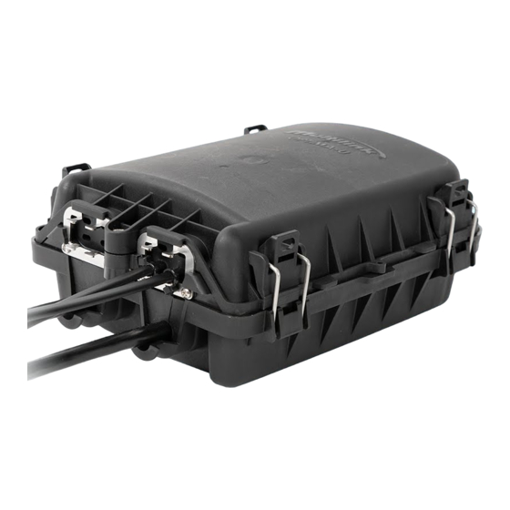
Optima™ U Enclosure
Table of Contents Continues on Page 2
Europe, Middle East & Africa
Tel: +1 440 366 6966
Fax: +1 440 366 6802
Email:
engsupport@gomultilink.com
All Rights Reserved
•
Latin & South America
Tel: +1 440 366 6966
Fax: +1 440 366 6802
Email:
lasupport@gomultilink.com
www.gomultilink.com
Scan
QR for
website.
3
3
4
5
6
6
Advertisement
Table of Contents

Related Manuals for Multilink Optima U


Summary of Contents for Multilink Optima U
-
Page 1: Table Of Contents
Tel: +1 440 366 6966 Contact Us | Fax: +1 440 366 6802 Fax: +1 440 366 6802 Fax: +1 440 366 6802 Email: engsupport@gomultilink.com Email: engsupport@gomultilink.com Email: lasupport@gomultilink.com © Multilink Inc. 2021 All Rights Reserved www.gomultilink.com Page 1 •... - Page 2 Optima™ U Distribution Installation 4.26 Fiber Drop Grommet 4.27 Install OptiDrop Fiber Connector 4.28 Gasket 4.29 Fasten Latches to Cover 4.30 Latch U-Base 4.31 Final Bolt 5. Accessory List © Multilink Inc. 2021 All Rights Reserved www.gomultilink.com Page 2 •...
-
Page 3: General
(such as home, apartment, or individual business). Connections can also be branched off to low count drop cables to feed another terminal point. Contact Multilink at (440) 366-6966 for assistance for FTTX network planning and FTTX deployment products. -
Page 4: Preparations
SILICONE SEALANT DISTRIBUTION LABELS • 1x Splice Tray Kit PRODUCT INFO CARD • 1x Hardware Kit 2.3 Recommended Handling of Fiber Follow your company’s guidelines for bend radius. • © Multilink Inc. 2021 All Rights Reserved www.gomultilink.com Page 4 •... -
Page 5: General Warnings
Be sure not to pull too hard on the fibers. Do not crush the cable or allow it to kink. Doing any of these things may cause damage to the fiber and require it to be replaced. © Multilink Inc. 2021 All Rights Reserved www.gomultilink.com Page 5 •... -
Page 6: Installation Entry Cable Preparations
Central Strength Member (CSM) UNLESS OTHERWISE SPECIFIED THIS DOCUMENT AND THE INFORMATION ultilink DIMENSIONS ARE IN INCHES CONTAINED THEREIN ARE CONFIDENTIAL & PROPRIETARY TO MULTILINK AND MAY NOT TOLERANCES ARE: ECN# DESCRIPTION OF CHANGE DATE BE COPIED OR DISCLOSED TO OTHERS... -
Page 7: Armored Cable
Repeat on opposite side of ring cut. 4.7 Drill Ground Lug Hole Drill a 0.25" hole into the center of the Optima™ U base indicated by the cutout on the bottom as shown. © Multilink Inc. 2021 All Rights Reserved www.gomultilink.com Page 7 •... -
Page 8: Insert Ground Lug
Insert the included fiber management clips into the slots of the Optima™ U base in the orientation shown. Ensure each clip is fully pushed in to prevent it from falling out in later steps. © Multilink Inc. 2021 All Rights Reserved www.gomultilink.com Page 8... -
Page 9: Proper Grommet Seal
Please note a recommended torque spec of 25-30 in-lbs. Once screws are inserted, tighten in the followng order: 1, 3, 2 until silicone oozes out and screws are properly secured. © Multilink Inc. 2021 All Rights Reserved www.gomultilink.com Page 9... -
Page 10: Install Csm & Cable Grommet
4.18 Attach Tie-Wraps Using the supplied tie-wraps insert into each fiber management clip on the upper side of the base to hold the branched off buffer tubes. © Multilink Inc. 2021 All Rights Reserved www.gomultilink.com Page 10 •... -
Page 11: Splicing Buffer Tube To Pigtail
(Multilink is NOT responsible for any damages or drastic light loss if splicing is not performed by a trained technician following the necessary instructions.) -
Page 12: Attach Splice Tray Cover
Remove the adapter cover and plug-in the pigtail connectors following the universal fiber color chart. DO NOT remove the adapter covers all at once. (Multilink is not responsible for any fiber loss that may occur if this is performed improperly.) 4.26 Fiber Drop Grommet... -
Page 13: Optima™ U Distribution Installation
An audible click confirms that the drop is secured. DO NOT remove all the adapter covers at once. (Multilink is not responsible for any fiber loss that may occur if this is performed improperly.) 4.28 Gasket... -
Page 14: Latch U-Base
(long end), as shown in the diagram below. 4.31 Final Bolt Finally, secure with bolt on the drop end of enclosure. Please note a recommended torque spec of 25-30 in-lbs. © Multilink Inc. 2021 All Rights Reserved www.gomultilink.com Page 14 •... -
Page 15: Accessory List
Accessory List Multilink’s Optima™ U supports various options of grommets accommodating vast cable diameters, additional accessories (some of which are included with the Optima™ U), and patch & splice options including installable kits and pigtails. Feeder Port Grommets Fiber Drop Grommets... - Page 16 Field Installable 066-025-10 Ground Lug Products Description Stock ID Grounding Lug 072-121-10 photo coming Grounding Kit for Optima U 072-757-20 Surelight® Field Installable Kits Products Description Stock ID Tool Kit w/ Beaver Cleaver 072-656-20 Tool Kit w/ Precision Cleaver 072-656-21 ©...
- Page 17 Tel: +1 440 366 6966 Tel: +1 440 366 6966 Contact Us | Fax: +1 440 366 6802 Fax: +1 440 366 6802 Mobile: +1 440 366 6802 lasupport@gomultilink.com Email: engsupport@gomultilink.com Email: engsupport@gomultilink.com Email: © Multilink Inc. 2021 All Rights Reserved www.gomultilink.com •...
Need help?
Do you have a question about the Optima U and is the answer not in the manual?
Questions and answers