
Subscribe to Our Youtube Channel
Related Manuals for CHNT Power NXM Series

Summary of Contents for CHNT Power NXM Series
- Page 1 NO:2021.04 NXM Series Moulded-Case Circuit-Breaker User Instructions Standard:IEC/EN 60947-2...
-
Page 2: Safety Warning
Safety Warning Installation in any damp, condensed-phase environment with inflammable and explosive gas is forbidden.Do not operate the product with wet hands. You are prohibited from touching the conductive part when the product is operating. When the product is being installed or maintained, the power must be switched off. -
Page 3: Use Information
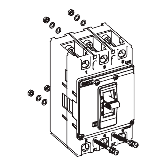
Use Information a) Ambient temperature for normal use: - 5 ℃ ~ + 40 ℃; Note: if it is used within the range of - 35 ℃ ~ + 70 ℃, please consult with the manufacturer b) If the altitude exceeds 2000m, please consult with the manufacturer; c) See the product sample for the inverse time lag, temperature compensation curve and altitude derating curve of the product;... - Page 4 Unit: mm Type Xmin NXM-63 Ensure NXM-125 minimum NXM-160 installation NXM-250 distance NXM-400 NXM-630 NXM-800 NXM-1000 NXM-1250 NXM-1600 Figure 2 Minimum installation distance ③ ① ② ④ ⑤ Making Breaking Making Tripping triping Figure 3 Test Overall and Installation dimension 2×φd 4×φd Figure 4-1 NXM-63~250 front-panel wiring overall and installation dimension...
- Page 5 Sectional view of wiring 6×φd Hmax Figure 4-2 NXM-63~250 front-panel wiring overall and installation dimension Table 1 NXM-63 250 overall and installation dimension Unit: mm Specification Dimen- Code NXM-63S NXM-63H sion NXM-160S NXM-160H NXM-250S NXM-250H NXM-125S NXM-125H 55.5 51.7 27.5 24.5 30.5 17.5...
- Page 6 Table 1 (Continued) Specification Dimen- Code NXM-63S NXM-63H sion NXM-160S NXM-160H NXM-250S NXM-250H NXM-125S NXM-125H Installa- tion dimen- 130.5 sion φd 4.5×6 Sectional view of wiring 4×φd 6×φd Hmax Figure 5 NXM-400 1600 front-panel wiring overall and installation dimension Table 2 NXM-400 1600 overall and installation dimension Unit: mm Specification Dimen-...
- Page 7 Table 2 (Continued) Specification Dimen- Code NXM-400 sion NXM-1250 NXM-1600 NXM-800 NXM-1000 NXM-630 Hmax 108.5 97.5 103.5 40.5 41.5 92.5 Installa- tion dimen- sion φd φd1 Figure 6 NXM-63~250 rear wiring Figure 7 NXM-400~800 rear wiring overall and installation dimension overall and installation dimension...
- Page 8 6×φd2 4×φd2 Installation Mounting plate hole Mounting plate hole dimension (3P) dimension(4P) diagram Figure 10 NXM series plug-in wiring overall and installation dimension Figure 11 NXM-63/125/400/ 630/800/1000 plug-in structure Figure 12 NXM-160 plug-in structure Figure 13 NXM-250 plug-in structure...
- Page 9 Table 3 NXM series back-panel wiring overall and installation dimension Unit: mm Specification Dimen- Code NXM-63 NXM-400 sion NXM-160 NXM-250 NXM-800 NXM-1000 NXM-125 NXM-630 —— —— —— 67.5 63.5 67.5 100.5 96.5 108.5 —— —— —— —— —— 44.5 ——...
-
Page 10: Installation And Wiring
Installation and Wiring c≤4 Cross sectional area : s NXM-63:s(b×c)≥16 NXM-125:s(b×c)≥50 Installation Connect to breaker 11≤X≤13 φ6.5 25.5 φ8.2 φ6.5 a≤7 a≤8 φ6.5 b≤17.5 b≤17.5 Figure 14 NXM-63/NXM-125 connecting plate and wiring dimension c≤5 Cross sectional area : s Connect to breaker Installation 25.5 s(b×c)≥70... - Page 11 30.5 c≤13.5 φ14 Cross sectional area : s φ14 wire Copper-bar 1 wire s(b×c)≥370 s(b×c)≥400 2 wires s(b×c)≥185 s(b×c)≥200 Installation φ10.5 19≤X≤21 φ10.5 φ10.5 30.5 φ10.5 a≤11.5 a≤11.5 Connect to breaker b≤30.5 b≤30.5 Figure 18 NXM-630 connecting plate and wiring dimension c≤12 φ17 Cross sectional area : s...
- Page 12 PUSH TO TRIP PUSH TO TRIP RESET RESET Figure22 -Motor driven mechanism overall and installation dimension Figure 23 -Wring of motor diven mechanism (AC) Table 4 NXM series motor riven mechanism overall and installation dimension Unit: mm Specification Dimen- Code NXM-63...
- Page 13 φ36 ° 2×φ5.5 Schematic diagram of handle installation NXM-63/125/160/250/ NXM-1250/1600 400/630/800/1000 Figure 24 Manual operation mechanism installation dimension Table 5 NXM Series manual operation mechanism installation dimension Unit: mm Specification Size NXM-63 NXM-400 NXM-1250 code NXM-160 NXM-250...
-
Page 14: Environmental Protection
Figure 28 Wiring of Figure 29 Wiring Figure 27 Wiring under voltage tripper of shunt tripper of alarm contact ① Flash barrier shall be installed before operation. ② Check if the wiring is correct. ③ After installation, the insulation resistance to the ground shall not Insert in the direction of the arrow be less than... - Page 15 QC PASS NXM Series Moulded-Case Circuit-Breaker IEC/EN 60947-2 Check 17 Test date: Please see The packing ZHEJIANG CHINT ELECTRICS CO., LTD.
- Page 16 NXM Series Moulded-Case Circuit-Breaker User Instructions Zhejiang Chint Electrics Co., Ltd. Add: No.1, CHINT Road, CHINT Industrial Zone,North Baixiang, Yueqing, Zhejiang 325603,P.R.China E-mail: global-sales@chint.com Website: http://en.chint.com...
Need help?
Do you have a question about the NXM Series and is the answer not in the manual?
Questions and answers