Advertisement
Quick Links
Advertisement

Summary of Contents for Vimar ELVOX 69PH
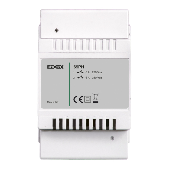
- Page 1 Installer manual 69PH Programmable device with 2 relays...
- Page 2 69PH CONTENTS Introduction ........................................................2 Description........................................................2 Technical characteristics ....................................................2 MANUAL programming standard Elvox DueFili BUS or VERTICAL BUS ....................................... 3 Programming with PROG. standard Elvox DueFili BUS or VERTICAL BUS....................................5 MANUAL programming HORIZONTAL Elvox DueFili BUS ..........................................9 Programming with PROG.
- Page 3 69PH MANUAL PROGRAMMING- VERTICAL BUS 1) Reset default data 2) Monostable relay with activation by buttons on the indoor stations (default config.) 3) Call repeater 4) ID assignment PROGRAMMING WITH PROGRAMMER ART. 950C OR "SAVEPROG" SOFTWARE - VERTICAL BUS 5) Monostable relay with activation by buttons on the indoor stations (default config.) 6) Call-activated monostable relay 7) Monostable relay activated by F1, F2 or lock buttons on the indoor station 8) Monostable relay activated by call attempt...
- Page 4 69PH Example: (Group 1 – indoor station ID = 8) 1) Set dip switch 4 in ON position to indicate programming. 2) Set dip switches 1, 2 and 3 on OFF to select GROUP 1. 3) Press and hold down P1 until the LED illuminates steadily. 4) Release P1.
- Page 5 69PH PROGRAMMING WITH PROGRAMMER ART. 950C / "SAVEPROG" - VERTICAL BUS 5) MONOSTABLE RELAY WITH ACTIVATION BY BUTTONS ON INDOOR STATION THIS is the factory set operating mode. The relays activate with a delay time T1 and remain active for a time T2 before returning to rest. Relay RL1 is activated by pressing button P2 on the indoor station, relay RL2 by pressing button P3 on the indoor station.
- Page 6 69PH 13) GENERIC CALL REPEATER The relay RL1 repeats the external call, the relay RL2 repeats the internal call. To do this, the ID of the GROUP must coincide for RL1 and RL2. When this does not occur even for only one of the relays (between RL1 and RL2), the check boxes EXT, INT and 6120 will appear in SaveProg to be checked for enabling.
- Page 7 69PH Functions Configurable parameters Monostable relay • 69PH identifier (see paragraph 4 “ID assignment”) • Operating modes = “DEFAULT” • Group 1 = 0 • Group 2 = 0 • Group 3 = 0 • Group 4 = 0 • T1 delay time (def.
- Page 8 69PH TABELLA PROGRAMMAZIONI EFFETTUABILI CON PROGR. ART. 950C O CON SOFTWARE “SAVEPROG” TABLE OF PROGRAMMING PROCEDURES POSSIBLE WITH PROG. ART. 950C OR “SAVEPROG” SOFTWARE Type of parameter Parameter selection Values Description 950C Save Prog 950C Save Prog Group “Group” “DEV. GROUP “GROUP”...
- Page 9 69PH PROGRAMMING RELAYS OVER HORIZONTAL BUS CAUTION: TO ACTIVATE THE RELAYS CONNECTED TO THE HORIZONTAL BUS, IT IS NECESSARY TO REMAP THE ROUTER 69RS ASSIGNING AN "EXTENDED" IDENTIFICATION ID (SEE ROUTER INSTRUCTIONS art. 69RS). THE EXTENDED ID CAN ONLY BE ASSIGNED VIA THE PROGRAMMER 950C OR SAVEPROG MANUAL PROGRAMMING 1) Reset default data PROGRAMMING WITH PROGRAMMER ART.
- Page 10 69PH 9) BISTABLE RELAY ACTIVATED BY ACCEPTED CALL The relay activates when a call is sent to a device present in the system, which then accepts the call. The relay can be deactivated differently according to the status of the “Int.Call” flag: - If the “Int.
- Page 11 69PH 950C programmer keypad: Button: to confirm (upon confirmation the message displayed reads “Done!”) Button: returns up a level or cancels typing Button: to quit programming Arrows button : to navigate from one menu to another and through the submenus. Numbers button : used to indicate the number of the Group and the ID, to select the language and to activate the flags.
- Page 12 69PH Programming with SAVEPROG software SaveProg is a PC software package supplied together with interfaces Art. 692I and 692I/U. Install the software on the PC. Launch the pro- gram by clicking on the icon. The image of Figure 5 is displayed. figura - figure 5 Select the icon highlighted by the arrow in Figure 6, the window appears where you can select the Relay 69PH EXTENDED).
- Page 13 69PH When the configuration is done manually, that is with the dip-switches, manual configuration prevails over any software configuration (with the programmer). Software assignment is therefore irrelevant. When the DIP switch is set to "0", you can assign the ID via the software configuration (with the programmer). ID 69PH With installation over vertical Bus it is possible to assign an ID code number from 1 to 8.
- Page 14 69PH Programming Diagram TERMINAL MODE Press for menu ENABLING MAP TYPE ITALIAN = ENGLISH = Press for menu RELAY 1 or 2 Window present only in INSTALLATION En.Map Type RELAY 1 or 2 “Vertical” configuration - with windows The parameter is changed by Enter to select the relay to be - single ID...
- Page 15 69PH Activ. Time Enabl. map Chime cycles Flag (0 - 20) Int.Call T.DelayOn (s) Internal Default 5 0=NO 1=YES Entrance panels T.On (s) Not.Status 0=NO 1=YES Auxiliaries Switchboards • To move from one menu to another press the buttons INTERNAL WIN# 1 Internal xxx 40000...
- Page 16 69PH Schema di collegamento con modulo programmabile 69PH per due servizi ausiliari / Wiring diagram with programmable module 69PH for two auxiliary services (SI646) Montante videocitofonico Video door entry cable riser 1° Relè 2° Relè Contatto C/NO/NC Contatto C/NO/NC Carico massimo 6A 230V Carico massimo 6A 230V 1st Relay 2nd Relay...
- Page 17 69PH The instruction manual can be downloaded from www.vimar.com Installation rules • Installation and configuration must be carried out by qualified persons in compliance with the current regulations regarding the installation of electrical equipment in the country where the products are installed.
- Page 18 Viale Vicenza 14 36063 Marostica VI - Italy www.vimar.com 49400649C0_MI_IT 00 2111...


Need help?
Do you have a question about the ELVOX 69PH and is the answer not in the manual?
Questions and answers