
Related Manuals for Rotec RTC.50-T

Summary of Contents for Rotec RTC.50-T
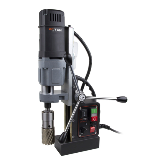
- Page 1 USER MANUAL TO REDUCE THE RISK OF INJURY USER MUST READ AND UNDERSTAND INSTRUCTION MANUAL RTC.50‐T Magnetic Drilling Machine SERIAL NO._______________ DATE OF PURCHASE _____________ ...
-
Page 2: Table Of Contents
1 ‐ Table of Contents 1 Table of Contents …………………………………………………………………………………………………… page 1 2 Safety …………………………………………………………………………………………………………………….. page 2 Before Use ……………………………………………………………………………………………………………… page 3 3 Items Included in Delivery ………………………………………………………………………………………. page 4 4 The Hole Cutter Hole Cutter Selection .................... page 5 Cooling/Lubrication .................... page 6 4 Tool Assembly Morse Taper Assembly …………………..………………………………………………………………… page 6 Hole Cutter Assembly …………………..………………………………………………………………… page 6 Drill Chuck Assembly ………………………………..……………………………………………………. page 7 ... -
Page 3: Safety
1. During any work on non‐horizontal components, the machine must always be secured with the supplied safety chain. 2. The magnetic drilling machine may only be used on a flat and clean surface. 3. If the machine or the lead shows signs of damage, the magnetic drilling machine must be switched off immediately. 4. Wearing safety glasses, hearing protection and protective clothing is necessary. 5. Do not wear any loose clothing or jewelry that may get entangled in the moving parts of the magnetic drilling machine. 6. Use only accessories or parts that are recommended by Rotec. 7. During drill operations, the hole cutter must be cooled and lubricated with good quality cutting or lubrication oil. 8. The motor must be switched off when tightening the machine with the safety chain. 9. When changing a hole cutter, the magnetic drilling machine must be disconnected from power supply. 10. Clean the area around the machine regularly. Keep the bottom of the magnet clean and dry. 11. Regularly inspect whether all screws, nuts and bolts are tight. 12. Remove the burr or slug from the hole cutter after each hole. Caution, the drill might still be hot! ... -
Page 4: Items Included In Delivery
Rotec magnet drilling machines are specifically designed for drilling holes in steel, expanded by the possibility of tapping/reaming/countersinking (RTC.50‐T). Rotec magnetic drilling machines are not suitable for applications other than those they were designed for, including driving other machines. Make sure that you can oversee the entire work area from where you are operating this machine. Use barriers to keep others away. Do not use the machine in places subject to hazard of explosion‐ electrical tools produce sparks which may ignite flammable materials or gasses. To prevent electrical shocks, do not use the machine in a moist or wet environment. Always operate this tool using both hands. Make sure the work piece is always clamped down safety. This magnetic drilling machine is equipped with a lead and plug approved for the country or region it is to be used in. The yellow‐green wire in the lead is the earth wire. Never connect this to a pole under voltage. All Rotec magnetic drilling machines are manufactured to use with AC current and not suitable to work on DC current. Make sure the magnetic drilling machine is connected to a stable power supply. Rotec does not recommend the use of a generator or other mobile power supply for power supply. Rotec does not recommend the use of extension cables. If there is no other way, use good quality cables and keep extension cables as short as possible. Be aware that long power leads cause less current. 3 ‐ Items Included in Delivery Magnetic Drilling Machine YES Pilot Pin NO Carrying Case YES Morse Taper YES Drill Chuck 13mm NO Morse Taper Ejector Pin YES Tap Collets M10‐M12‐M14‐M16 NO Manual YES Allen Key 2.5 YES ... -
Page 5: The Hole Cutter
536.xxx0 12 mm ‐ 60 mm Hole cutters with cutting depth 25 mm increasing by 1 mm 536.xxx1 12 mm ‐ 60 mm Hole cutters with cutting depth 50 mm increasing by 1 mm Rotec Gold‐Line 537 For processing steel, stainless steel and other high‐quality steel alloy types 537.xxxx 12 mm ‐ 60 mm Hole cutters with cutting depth 30 mm increasing by 1 mm 538.xxx0 12 mm ‐ 60 mm Hole cutters with cutting depth 55 mm increasing by 1 mm 538.xxx1 18 mm ‐ 50 mm Hole cutters with cutting depth 80 mm increasing by 1 mm ... -
Page 6: Cooling/Lubrication
Holes for cooling and lubrication oil 2 Fixing screws of Morse Taper Rotec recommends the use of cooling and lubrication agents. Not only do these assist in drilling but they will also lengthen the lifespan of your tools. One of the advantages of the use of hole cutters is that cooling and lubrication agents can be supplied from the inside, so that the agents end up in the right place. All magnetic drilling machines from Rotec can be equipped with an automatic cooling system which provides a guaranteed supply of the cooling and lubrication agents from the inside. If your machine is not equipped with an automatic coolant system it is still possible to cool from the inside by using the holes in the Morse Taper (number 1 in picture) by squirting the cooling and lubrication agent through them and filling the Morse Taper. NOTE : For vertical or upside‐down processing, Rotec recommends the use of a drilling compound or paste like 901.4045 or 901.4046. 4 ‐ Tool Assembly Morse Taper Assembly Mount the Morse Taper into your machine by pushing it firmly into the shaft extending from the motor unit. Beware that the tip on top of the Morse Taper is in line with the shaft. To take the Morse Taper out use the Ejector Pin to force it out. Hole Cutter Assembly ... -
Page 7: Drill Chuck Assembly
Drill Chuck Assembly The option of making our machines suitable for the use of standard spiral drills and other tools by using a cylindrical shaft is an important characteristic of Rotec magnetic drilling machines. Please see the technical data for maximum capacity. Installation of 13mm Chuck by using adapter IBK.14 The 545.1021 is a adaptor from 1/2"x20 UNF to 19mm Weldon. Attach a Drill Chuck with internal 1/2"x20 UNF on the 545.1021 adaptor. To attach the assembly into your Spindle, follow the instructions (with exception of the Pilot Pin) for installation of a Hole Cutter. Adaptor IBK.14 can be used on most machines in our program. Installation of 13mm Chuck directly on the motor unit For the RTC.50 magnetic drilling machine it is possible to install a drill Chuck directly to the shaft extending from the motor unit. Attach to the drill chuck with article number 181.1005 a adaptor with article number 180.2016. This way the drill chuck can be mounted as a Morse Taper in your machine. 4 ‐ The Magnetic Drilling Machine The Magnetic base Material of minimum 10mm thickness is required for the magnet to work the best. The attachment force generated by the magnet depends on various factors. ‐ Thickness of the material the magnet is placed on ‐ Paint or coating of the material the magnet is placed on. ‐ Metal chips, oil or other dirt under the magnet. If the LED indicator lights up GREEN, the magnet is generating sufficient attachment force. If the LED indicator lights up RED, the magnet may not generating sufficient attachment force. We would like to point out that this is only an indication and not a certainly that the magnet will not release from the material. Rotec accepts no liability ensuring from the magnet indicator not functioning or functioning poorly. Make sure that the magnet attaches tightly to the work piece before turning on the motor unit of the ... -
Page 8: The Control Panel
The Control Panel The control panel on your magnetic drilling machine is designed for maximum operating facility and safety. 1 ‐ The Magnet Switch: This switch is used to switch the main power and also the magnet On and Off. This switch is included on every Rotec magnetic drilling machine 2 ‐ The On/Off Switch: This switch is used to switch the motor unit On and Off and is included on every Rotec Magnetic Drilling Machine 3 ‐ The Fuse holder with Fuse: This Fuse holder is included on every Rotec Magnetic Drilling Machine and holds the fuse type : 5x20, F2A. 4 ‐ The Magnet LED Indicator: This LED indicator shows the generated magnetic force. 5 ‐ The L/R Switch: This switch controls the direction of the motor unit. 6 ‐ The Potentiometer: This controls the running speed of the motor unit. Note that a lower position will decrease the power of the motor unit. Continuous electronic Torque protection: The RTC.50T is equipped with a all‐time electronic torque protection. It will stop the motor unit when it gets overloaded in any rpm. In that case just push the OFF switch to reset and ON switch to start drilling again. Continuous electronic Temperature protection : The RTC.50T is equipped with a all‐time electronic temperature protection. If the temperature of the motor unit runs up to 70 Degree Celsius the motor unit will stop. After a few minutes it can be started again and we recommend to let the motor run unloaded with the electronic speed adjustment set on 100% to let the motor unit cool down. !!! IMPORTANT !!! When using your magnetic drilling machine non‐horizontal or upside‐down be aware ... -
Page 9: Maintenance
Apply less pressure when the drill cuts through the material. 9 Turn the arms to put the motor in highest position and turn off the motor unit. 10 Remove the burr, metal chips and clean the cutter and surface without getting injuries. Caution : The metal piece drilled out can be sharp and very hot!! The RTC.50‐T have a 2‐speed gearbox and a electronic speed adjustment. To prevent heat build‐up always try to keep the electronic speed adjustment as high as possible. Use the upper gear (high) for hole cutters up to 20 mm and the lower gear for hole cutters above 20mm. The RTC.50‐T have a fully electronic motor unit which measures its speed continuously to have the maximum power available. When you start drilling the RPM can go down for a moment until the machine itself will increase the RPM. This is completely normal. To select another gear, turn off the motor unit and the main power. Push the black switch on the side of the gearbox and slide it to the other position. A slight turn of the output shaft by hand while sliding the black switch to the other position, can be necessary to line up the gears inside. Proof that the gear is locked if the black switch comes back to front. Tapping 50T Drill the hole on the recommended size of the tap. Do not turn the magnet off to keep the machine on its position. Take the cutter out and use a tap collet to fix the tap to the machine. These adapters exist in several DIN and ISO norms and are based on the shaft diameter of the tap that is used. Use the low gear and low rpm for tapping. Stop the machine manually before the tap is completely through the hole. Select the Reverse (Left) and let the tap run back slowly but also support the run back by turning back the handles. Do not let your tap push back the motorunit by itself! If your tap have to make the whole way through the material, then remove the tap out of the collet when the hole is completely tapped. !!! IMPORTANT !!! When using your magnetic drilling machine non‐horizontal or upside‐down be aware that no oil, drilling compound or metal chips can fall into the motor unit. Rotec accepts no responsibility for damage done to your machine by such action under coverage of the warranty. 5 ‐ Maintenance 9 ... - Page 10 damage. The guide can be adjusted by loosening the setting nut (#7 on spare part drawing) with included wrench 8, tightening the setting screws (#5 on spare part drawing) with included Allen key 2.5 and tightening the setting nut (#7) again with included wrench 8. The adjustment is done well when the motor unit can be turned to every possible position without falling down by its own weight. ‐ Check the grease in the gearbox regularly and replace it if necessary. We recommend you to store your machine on its side regularly so that the gear box grease can run back to where the gears are. This is very important when you have used your machine non‐horizontal or upside down. Repair, modification and inspection of Rotec Magnetic drilling machines must be done by a Rotec authorized dealer. The parts list will be helpful if presented with the machine to the Rotec dealer for service when requesting repair or other maintenance. Rotec machines are constantly being improved and modified to incorporate the latest technological advancements. Accordingly, some parts (ie part numbers and/or design) may be changed without prior notice. Also, due to Rotec's continuing program of research and development, the specifications of machines are subject to change without prior notice. ...
- Page 11 6 ‐ Spare parts & Exploded view of RTC50 Frame Screw 3,9x60 Screw SSM6x16 Adaptor ring 22x0,2 Washer M6 Needle bearing Setting Nut Bearing 8x22x7 Setting Screw Bearing 12x28x8 Magnet Hi/Lo First gear Sensor Axle Slide Gear shaft Rack Spindle drive shaft Screw SSM6x20 Carbon brush holder Motorholder Carbon brush set Screw SSM6x25...
- Page 12 12 ...
- Page 13 Important notice : Because of minor changes to our machines it is recommended to provide the frame number of your machine when ordering spare parts. This number can be found on front of machine at magnetic base and frame. When you have any doubt when ordering spare parts, please contact your supplier before ordering. 13 ...
Need help?
Do you have a question about the RTC.50-T and is the answer not in the manual?
Questions and answers