Table of Contents
Advertisement
Quick Links
Battery/Tank Monitor BTM2
Thank you for purchasing the Battery / Tank Monitor BTM2.
This gives you one of the most advanced and accurate battery / tank monitors available on the
market.
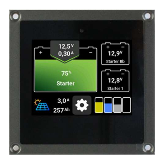
Battery monitor:
You can see at a glance:
- the current state of charge
- charge and discharge currents
- the battery voltage
- the remaining operating time until the adjustable capacity alarm of the main battery
- the voltage of up to 2 additional batteries
- the currents of a solar system and the charger (optional)
and have the possibility
- connect a second shunt SHP to measure e.g. the current of the solar system.
- connect a philippi charger ACE to monitor the charging process.
- set an alarm when the capacity of the main battery falls below a threshold
- set an alarm when the voltage falls below or exceeds a threshold.
- connect the monitor to an NMEA 2000 network and display the battery and tank levels on the
plotter.
Tank monitor:
You can see at a glance
- the current fill levels of up to 4 tanks
and have the possibility to
- set an alarm threshold for each tank (full or empty alarm)
philippi elektrische systeme gmbh
Neckaraue 19
D-71686 Remseck am Neckar
OPERATING INSTRUCTIONS
Battery/Tank Monitor BTM2
www. philippi-online.de
info@philippi-online.de
Tel: +49 (0)7146/8744-0
Advertisement
Table of Contents

Related Manuals for philippi BTM2


Summary of Contents for philippi BTM2
- Page 1 Battery/Tank Monitor BTM2 OPERATING INSTRUCTIONS Battery/Tank Monitor BTM2 Thank you for purchasing the Battery / Tank Monitor BTM2. This gives you one of the most advanced and accurate battery / tank monitors available on the market. Battery monitor: You can see at a glance:...
- Page 2 The battery/tank monitor is not suitable for outdoor installation. 1.2 L Scope of delivery - Battery/Tank Monitor BTM2 - 3 Plug-in terminals (2x MVSTB 2.5- 3 and 1x 9-pole)
-
Page 3: Warranty
Compliance with the operating instructions as well as the conditions and methods during installation, operation, use and maintenance of the battery/tank monitor BTM cannot be monitored by philippi elektrische systeme gmbh. Therefore, we do not accept any responsibility or liability for losses, damages or costs resulting from incorrect installation and improper operation. -
Page 4: Assembly And Installation
Battery/Tank Monitor BTM2 - No modifications may be made to the unit, otherwise the CE mark - The battery/tank monitor may only be connected by qualified electricians. - Before connecting the battery/tank monitor, disconnect the battery leads. - Ensure that the polarity of the batteries is correct! - The power supply line to the monitor and shunt must be fused. - Page 5 Battery/Tank Monitor BTM2 The LIN bus connection between the monitor and the shunt is made via a 1-wire cable. This can also be any or an existing cable. For mechanical reasons, the cable cross-section should be min. 1mm² and max. 1.5 mm².
- Page 6 Battery/Tank Monitor BTM2 3.2 Shunt SHE for battery monitoring Mount the shunt SHE 348 in a protected, dry place as close as possible to the battery. The shunt must be connected in the MINUS path of the battery. Install the active shunt SHE 348 as close as possible to the service battery. However, avoid the shunt making contact with the positive - terminal of the batteries.
- Page 7 4: LIN bus communication with display The BTM2 monitor communicates with the SHP shunt via this line. This line can be realised with any cable, preferably with 1 mm² cross-section. 3.4 Interface ACE-LIN (optional accessory) To communicate the BTM2 monitor with an ACE series charger, an ACE-LIN interface must be inserted into the ACE charger.
- Page 8 Battery/Tank Monitor BTM2 Remove the cover Break out the metal tongue with flat-nose pliers Inserting the rubber cable grommet Inserting the cover and the cable. Inserting the interface board ACE-LIN Make sure that the ACE charger is disconnected from the AC mains before starting work.
- Page 9 Battery/Tank Monitor BTM2 The interface board is held in place by three plastic clips on the housing. Wiring LIN line to monitor BLS / shunt SHE The communication connection "LIN" of the interface ACE-LIN is connected to the connection "LIN"...
- Page 10 Battery/Tank Monitor BTM2 3.5 Electrical connection tank sensor Up to four tanks can be monitored simultaneously. However, if fewer tanks are monitored, the first tank sensor is connected starting at connection TG 1 (e.g. with 2 tank sensors, only connections TG 1 and TG 2 are used).
- Page 11 Battery/Tank Monitor BTM2 The following settings can be made by pressing the respective symbol: Display Battery Charger Energy source Tanks Alarms 4.2 Display After pressing the "Display" symbol, the adjacent picture appears. The following settings can now be made or information read off: Language DE/FR/GB...
-
Page 12: Battery Management
Battery/Tank Monitor BTM2 The setting "Threshold night mode" is used to calibrate the light sensor in automatic mode. For calibration, the light sensor (left centre of the display) must be covered with the finger and the value in brackets must be read. Add two to this value and enter it by pressing briefly. If the measured value falls below the set value, the display is dimmed. -
Page 13: Rated Voltage
Battery/Tank Monitor BTM2 4.3.2 Nominal capacity The nominal capacity of the battery (1-9999Ah) is set here. To obtain a meaningful accuracy of the remaining time function as well as the percentage charge display, the capacity of the battery to be monitored must be set. - Page 14 Battery/Tank Monitor BTM2 Usually, the Peukert exponent is set to 1.27 for lead batteries, if no deviating values are available, and to 1.02 for lithium systems. 4.3.8 Name2 This name is displayed in the battery symbol of the additional battery and is used for clear assignment.
- Page 15 Battery/Tank Monitor BTM2 If no philippi ACE series charger is connected or the charger is not supplied with mains voltage, no settings can be made. 4.5 Alarm A tank alarm is always indicated by the associated tank symbol flashing. A battery alarm is always displayed in the battery symbol.
- Page 16 Battery/Tank Monitor BTM2 Battery capacity alarms A message appears on the monitor to charge the battery (battery appears red) if the battery falls below the set capacity threshold. The alarm for the alarm capacity is preset to 50%. For an average application, this value is usually fine;...
- Page 17 DFS - (down) philippi DFSFlow sensor not possibleDFS (up) philippi DFS flow sensor not possible TRS / RSW / DSW philippi TRS / RSW / DSWFloat switch not possible REV 1A - FEB 2022 - Software Version 1.xPage 17...
- Page 18 TRIM menu. Tank sensor: This setting option only works with passive resistance tank sensors, not with capacitive tank sensors or active resistance sensors (e.g. philippi UTR) ! 4.6.3.5 SENSOR TYPE USER V (UTV) With this setting, tank sensors can be displayed with a voltage signal in the range of max. 0 - 10 volts.
- Page 19 0, 25, 50, 75 and 100%. 4.6.3.8 SENSOR TYPE DFS - For this setting you need a philippi DFS flow sensor. The connection is only possible to DFS S. The following symbol appears under the respective tank in the main menu: Since this sensor cannot detect whether the tank is being filled, you must enter the fill level manually.
-
Page 20: Reset Counter
Battery/Tank Monitor BTM2 respective default settings from the selected sensor type can be adapted to the individual conditions. This is mandatory for the tank types User R, User U, TDS: Method 1 (tank is filled step by step): the probe is in the empty tank. In the Setup menu, go to the setting value for 0% and read the measured value in the middle at the bottom and enter it in the Level 0% field. - Page 21 Instance 0 is usually selected by default. However, if the data on your chart plotter is not displayed or is on the wrong page, you should select a different instance for the Philippi unit. If there are 2 Philippi units on the network, different unit instances must be set on each unit (see Setup Monitor Display).
-
Page 22: Operation
5. operation On the main page, you can switch between the 3 main screens using the lower buttons: Tank / battery and charger, if a philippi charger ACE with interface ACE-LIN is installed. Otherwise, only the battery/tank screen is available. - Page 23 Battery/Tank Monitor BTM2 SETUP: The settings for the battery system can be made here. See chapter 4. The tank screen shows the individual tank levels. The measurement takes place automatically after the monitor is switched on and is interrogated every 5s. The measured values are displayed in the form of a bar chart.
- Page 24 The charging screen shows the operating status of the active philippi charger ACE. If the ACE charger is disconnected from the mains or if no charger is connected, the screen is not active and cannot be selected.
-
Page 25: Battery History
Battery/Tank Monitor BTM2 Night mode: On units with an active fan, the fan can be switched off to enable silent operation. The max. charging current is limited to the thermal conditions of the charger. This function is automatically deactivated after 8 hours. -
Page 26: Reset The Counters
Battery/Tank Monitor BTM2 The average depth of discharge indicates by how much the battery group was discharged on average in the past 10 cycles. From this, the cycle load of the battery can be read and a conclusion drawn about the battery life. -
Page 27: Software Update
Battery/Tank Monitor BTM2 The detection of the unavailable capacity is only possible if the battery is discharged up to the first discharge limit (depending on battery type & load, below approx. battery voltage < 11.5 V). If the battery is never discharged to this first discharge limit, this detection cannot take place and a 100% intact battery is assumed. -
Page 28: Technical Data
Battery/Tank Monitor BTM2 update process, the progress is displayed. If the monitor starts normally after inserting the SD card, no SD card has been detected or the software is up to date. 8. Technical data Supply voltage DC 8-60 V Monitor power consumption 60 mA at max.
Need help?
Do you have a question about the BTM2 and is the answer not in the manual?
Questions and answers