
Related Manuals for Framers Corner M3


Summary of Contents for Framers Corner M3
- Page 1 Operators Manual M3 Manual Underpinner Only Use Genuine Framers Corner Universal Wedges Our Wedges are 10.3mm Wide, Available In Softwood And Hardwood Type.
-
Page 2: General Safety Rules
M3 Technical Specification Moulding Width (Using Rebate Clamp) 0-60mm Moulding Width (Without Clamp) 0-100mm Moulding Height 0-100mm Pin Placement from Back Corner 0-110mm Wedge Sizes 7 to 15mm Underpinner Dimensions (WxDxH) 730mm x 800mm x 1110mm Weight 30kg Warranty 1 year... - Page 3 Unpacking Your Underpinner Check the contents have arrived safely and all the components are present according to the list below. Large Parts A) Front Stop Bar G) Round Pad B) Clamp Adjuster H) Left Table C) Vertical Bar I) Front Clamp D) Handle J) Right Table E) Washer...
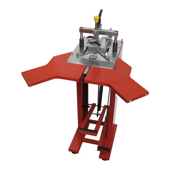
- Page 4 MAIN FEATURES OF THE M3 UNDERPINNER Clamp Height Top Clamp Lock Adjuster Fence Lock Top Clamp Pad Front Wedge Position Lock Front Clamp Rear Wedge Sliding Fence Position Lock Main Table Magazine Feeder Side Table Anchor Bolt ASSEMBLY INSTRUCTIONS 1) Fit the Rubber Feet...
- Page 5 Place the Brass Nipple (S) into the threaded Push the adjusting button inwards and insert, hole in the fence block. from above, the Vertical Bar (C). Screw the L Shaped Pad (F) onto the end of the vertical bar. Screw in the Locking Handle (R). 4) Assemble the Front Clamp Position the Front Clamp (L) so that one of the round holes aligns over the Clamp Pusher.
- Page 6 OPERATING INSTRUCTIONS 6) Remove the Footpedal Locking Clamp For safety during transport the main pedal is 1) Set the Fence locked down. Undo the handle and slide the The fence will slide smoothly forward and back. Locking Clamp upwards, allowing the pedal to This allows wedges to be inserted into any move up at the same time.
- Page 7 Single Stacked Wedge Wedges 3) Select the Appropriate Sized Wedge The M3 can use wedge (V-nail) sizes 7mm, 10mm, 12mm and 15mm. Please Note: Only use Genuine Framers Corner Universal wedges 10.3mm Width, supplied in glued strips. Page 7...
- Page 8 Use the Magnetic Tool (T) to pull the partly used strip of wedges, out of the magazine. Insert a strip of wedges, sharpened side up- wards. When using genuine Framers Corner Wedges, insert with glued side up. 5) Set the Front Clamp The front clamp grips the moulding by the rebate.
- Page 9 8) Insert the Wedge 6) Choose the Appropriate Rubber Pad The pinner is supplied with 2 rubber pads. For With all the above settings made: flat moulding the round pad is generally better. Push the fence into the back position For profiled moulding with varying heights the L shaped pad is generally better.
-
Page 10: Routine Maintenance
We declare that Manual Underpinner, When refitting the cap, ensure the top is flush Model M3 conforms with the following with the surface of the surrounding table. directives: 3) Replacing the Driver... -
Page 11: Troubleshooting Guide
TROUBLE SHOOTING GUIDE Page 11... - Page 12 Page 12...
- Page 13 M3 Parts List No.1 - General Layout Part No. Part Code Part Description UP1124 Floorstand F1016 2 x M8 Nut UP1451 Cable Adjuster F1009 M6 Adjustable Handle UP1141 Footpedal Height Adjusting Bracket F1016 4 x M8 Nuts F1017 8 x M8 Washers...
- Page 14 M3 Parts List No.2 - Operating Head Part No. Part Code Part Description F1020 M8 Socket Head Screw F1022 2 x M10 Socket Head Screws UP1114 2 x Trunnion Bar F1013 4 x M6 Socket Head Screws UP900 Left Hand Fence Block...
- Page 15 UP954 Driver Support UP957 Driver UP678 M6 Nut F1015 Wedge Platform Adjusting Knob UP1462 M3 Parts List No. 4 - Horizontal Clamp Part Code Part Description Part No. UP1130 Horizontal Clamp Bar UP609 Jaw Pivot F1013 M6 Socket Cap Head Screw...
- Page 16 M3 Exploded View No.1 General Layout Page 16...
- Page 17 M3 Exploded View No.2 Operating Head Page 17...
- Page 18 M3 Exploded View No.3 Magazine Page 18...
- Page 19 M3 Exploded View No.4 Horizontal Clamp Page 19...
Need help?
Do you have a question about the M3 and is the answer not in the manual?
Questions and answers