Advertisement
Quick Links
Advertisement

Related Manuals for Fly Dragon FDG30

Summary of Contents for Fly Dragon FDG30
- Page 1 FDG30 Mako Shark mapping survey VTOL UAV User-Manual V1.0 CHENGDU FLYDRAGON AVIATION TECH CO., LTD...
- Page 2 Purpose of this manual This is the user manual of FLYDRAGON FDG30 VTOL UAV, This user guide explains in detail how to install, configure, and use the FDG30 VTOL UAV drone, and use the UAV GSC ground station software to perform video control-free operations on the FDG30 VTOL UAV.
-
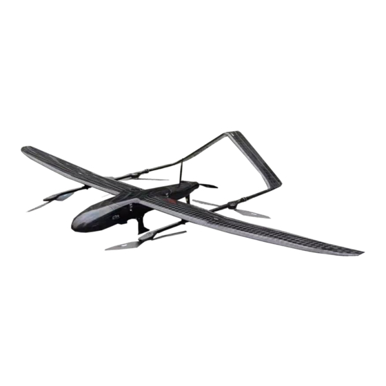
Page 3: Product Introduction
REDUCE OPERATING COSTS AND SAVE TIME No more systematic ground control points (GCP) required. The FDG30 integrates a high-accuracy GNSS RTK / PPK module that has up to 10... - Page 4 The application scenarios of the FDG30 Mako Shark UAV system are based on the application of various large-area topographic surveys (water conservancy, highways, railways, various scale topographic maps), electric power site selection, engineering construction / patrolling (roads and bridges) and other private surveying and mapping industry units and related applications.
- Page 5 1.2 UAV GCS software installation 2. Safty flight 2.1 Connect to UAV Connect the battery to the aircraft and enter the aircraft self-check; ★Attention After the aircraft is assembled and the battery is connected, the aircraft will automatically calibrate each sensor and the autopilot will detect it autonomously. Do not shake the aircraft at this time (shaking the aircraft will cause the gyro calibration to fail or cause errors)
- Page 6 Click on "Connect Drone";...
- Page 7 The ground station software will automatically connect to the aircraft and upload aerial survey tasks; the aircraft status can be monitored in real time through the aircraft indicator lights, the following table shows the aircraft status under different indicator lights; Light status Drone status Remark...
- Page 8 2.2 Pre-flight inspection Select "Check" in the control bar at the bottom of the ground station, The ground station will pop up a check list window, check in the order of the list and check the checked rows, then click "Next" to complete all checks.
- Page 9 2.3 Takeoff Tutorial 2.3.1 Set Landing Point After completing the check, the "Check" button becomes "Set Landing Point" Place the aircraft at the landing point (it must be far away from the propeller), click "Set landing point", and click "OK" to complete the landing point setting; 2.3.2 Unlock After completing the "Set Landing Point", the "Setting Landing Point"...
- Page 10 2.3.3 Take off After unlocking, the propeller will start to idle immediately, and after idling for 5 seconds, it will automatically perform vertical take-off. 2.3.4 Monitoring and control (1) Flight monitoring The flight status of the aircraft can be monitored in real time through the ground station.
- Page 11 ★Attention The waypoints, aerial survey points and flight paths of the aircraft are stored in the UAV flight control system. If the ground station loses contact with the aircraft, the aircraft will perform the flight mission according to the original aerial survey plan by default.
- Page 12 3. Aerial survey mission planning The aerial survey operation requires strict compliance with local laws and regulations, and it is strictly forbidden to set the aerial survey area in the no-fly area. Users need to do a field inspection of the operation area in advance to understand the local topography, urban layout and population density, etc., to provide a basis for the selection of take-off and landing sites and route planning.
- Page 13 Click the aerial survey tab on the right, a shaded polygon area can be seen in the map display area of the ground station, click and drag the shaded area to the desired aerial survey position, click the edge of the polygon to increase the vertices of the polygon, and adjust by dragging the vertices of the polygon The scope and shape of the aerial survey area.
- Page 14 3.1.2 Set the aerial survey parameters In the aerial survey tab, set the resolution, flight height, route angle and overlap rate according to the aerial survey requirements. The flight altitude and the resolution affect each other. The larger the ground distance represented, the larger the single operation area.
- Page 15 ⚫ hint: Increasing the horizontal overlap rate increases the density of routes, and the operating area per unit time will decrease. Recommendation: The default heading overlap rate is 75%, and the lateral overlap rate is 60%. If you want to achieve higher quality results, it is recommended that the vertical overlap rate is not less than 80%, and the horizontal overlap rate is not less than 65%.
- Page 16 Introduction to the intelligent low-voltage return-to-home function: The flight controller comes with a low-voltage return-to-home function. The intelligent return-to-home voltage will be calculated in combination with the current return distance to ensure that the aircraft has enough power to land safely without worrying about flight accidents due to insufficient power.
- Page 17 3.1.3 Export or load tasks After the aerial survey task setting is completed, click "Export Task" in the UAV menu bar, select the save path to save the aerial survey task, and also select "Load task" to load the aerial survey task and use it directly. ⚫...
- Page 18 3.2 Advanced features of aerial survey planning 3.2.1 Multi-region task generation The UAV GCS ground station supports flying multiple independent areas in the same mission. The operations are as follows: After generating an aerial survey area task according to the above operation, you can click the aerial survey tab on the right again, drag the aerial survey shadow area and adjust the polygon shape (same as above), Set the aerial survey parameters (same as above), click to generate waypoints, the ground station will prompt "whether to clear the existing...
- Page 19 ▼ Attention This function is different from flying in different sorties. The planned multi- measurement area tasks will all be uploaded to the UAV waypoint list, and the UAV will automatically execute the waypoint tasks in sequence until all the waypoint tasks are completed.
- Page 20 3.2.3 Save and load sub-division measurement areas Save sub-division measurement areas independently, flexibly combine and load, which can be used for task assignment of multiple operation groups and can also be used for operation planning by period. When planning a mission, you only need to save each survey area separately. During the actual flight, you can flexibly combine and load the independent survey areas into the same task.
- Page 21 3.2.5 Supplementary flight for some missions If a certain survey area mission needs to be supplemented due to weather or other factors (for example, it needs to be supplemented between waypoint 5 and waypoint 11), you can right-click waypoint 5 after takeoff and reach the take-off circle point, and click "...
- Page 22 4. Fly Mission 4.1 Take-off and landing site selection (1) Take-off clearance requirements The take-off clearance requirements are in the blue area as shown in the figure below. It must be ensured that there are no obstacles in the blue area. The radius of 50 meters in front of the take-off point, and the fan shape of 30°...
- Page 23 4.2 Set task/load task Method 1: Load a saved task, select "Load Mission" in the UAV tab to load the planned aerial survey mission. Method 2: The mission can be planned on site, see the chapter "Aerial Survey Mission Planning" for details. After the waypoint mission is generated, the mission will be automatically uploaded to the aircraft autopilot.
- Page 24 performing a mission in the air, the ground station will automatically download the mission from the aircraft side to achieve synchronization after reconnecting the aircraft. (Applicable to unexpected situations such as computer crash, computer power failure, software crash, etc., the computer can be temporarily replaced to achieve ground station task synchronization without affecting flight safety).
- Page 25 mission waypoint 1 to ensure flight safety. ★Takeoff circle point settings Drag the take-off circle point directly to a suitable position in the map display area of the ground station. Since flying against the wind will help the aircraft fly to the take-off circle point more smoothly, it is recommended to set the take-off circle point at 200-300 meters in the upwind direction of the take-off point.
- Page 26 degrees) from the direction of the planned takeoff path, to ensure that there is no takeoff and landing direction planning due to unfamiliarity with the direction of the site mistake. 4.5 VTOL UAV Landing ★Landing hover point settings This point is used as the safe circling point for returning home, and it is also the safe circling position when the aircraft is flying in an emergency.
- Page 27 4. Perform automatic conversion of the multi-rotor, and slowly approach the top of the landing point; 5. Perform a vertical landing. The landing is carried out in two stages. The first stage is faster (3.5m/s by default). When the height drops to the second stage (6 meters by default, can be set), the landing speed will be reduced to a slower speed.
Need help?
Do you have a question about the FDG30 and is the answer not in the manual?
Questions and answers