Table of Contents
Advertisement
Quick Links
DOCK LEVELER
WITH TELESCOPIC LIP SERIE DS/DSI
Original installation and operation instruction
© DoorHan, 2015
MANUFACTURER'S DECLARATION
OF CONFORMITY
GENERAL INFORMATION
SAFETY RULES
SAFETY FEATURES
GENERAL VIEW
INSTALLATION
OPERATION
MAINTENANCE
TROUBLESHOOTING
APPENDIXES
2
2
3
4
5
6
PACKAGE
6
10
11
12
13
Advertisement
Table of Contents

Related Manuals for DoorHan DS Series

Summary of Contents for DoorHan DS Series
- Page 1 MANUFACTURER’S DECLARATION OF CONFORMITY GENERAL INFORMATION SAFETY RULES SAFETY FEATURES GENERAL VIEW PACKAGE INSTALLATION OPERATION MAINTENANCE TROUBLESHOOTING APPENDIXES DOCK LEVELER WITH TELESCOPIC LIP SERIE DS/DSI Original installation and operation instruction © DoorHan, 2015...
-
Page 2: Table Of Contents
Appendix 3. Pits for dock levellers ........23 1. MANUFACTURER’S DECLARATION OF CONFORMITY Manufacturer: LLC StoreHan, 143002, Russia, Moskovskaya obl., Odintsovskij r-n, s. Akulovo, ul. Novaya, d. 120 Trademark: DoorHan Dock levellers serie DS/DSI fulfil the stipulations of the Machinery Directives... -
Page 3: Safety Rules
SAFETY RULES FUNCTION Function DCUT-1 DCUT-2 DCUT-3 Impulse AUTO button 400Volt Traffic light outside Traffic light inside Dock light Interlock (door-dockleveler) Extra safety devices connection Service indicator Digital display Door control Inflatable dock shelter control 3. SAFETY RULES The improper use is not allowed. Provide good lighting and visibility when operating the dock leveler. -
Page 4: Safety Features
SAFETY FEATURES 3. SAFETY FEATURES Rising/lowering speed less than 0.15 m/s. Maintenace supports ensures safe maintenance and connection of wiring. Burst valve immediately stops upper deck in case of hose rupture. All hydraulic components designed to resist to a pressure at least double than declared one. -
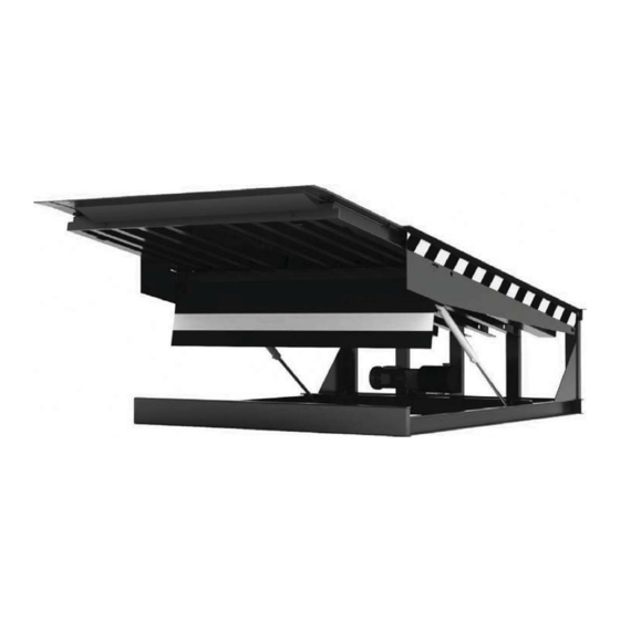
Page 5: General View
GENERAL VIEW 4. GENERAL VIEW 1. Upper deck 2. Lip 3. Frame 4. Signal yellow-black stripping 5. Hydraulic pump 6. Lifting cylinder 7. Lip cylinder 8. PVC front curtain 9. Control unit WARNING Upper plate of the dock leveller is a 8-10 mm thick steel sheet with lentiform (diamond) riffling with height 0.8–3 mm. If load- ing/unloading is performed using a standard 4-wheel forklift with inflatable tyres, the dock leveller is manufactured with 8 mm thick sheet and riffling height 0.8–2.4 mm. -
Page 6: Package
GENERAL: Make the installation in accordance to all local safety regulations! The installation of the dock leveller must be carried out by the service department of DoorHan or by a service department/dealer recognized by DoorHan. When installing the dock leveler in the pit, fix the lifting belts only in certain points. - Page 7 INSTALLATION EMBEDDED MOUNTING WITH TAIL LIFT ACCESS 2а 1. Stretch the connection wiring through the tube. 2. Install the dock leveler so that the rear corner of the dock leveller tightly adjoined to the rear upper fitting on the pit. 3.
- Page 8 INSTALLATION Gap between the pit and the dock leveller 10–15 mm on both sides. Рис. 3a Fig. 3a SUSPENDED MOUNTING 2а...
- Page 9 INSTALLATION 1. Stretch the connection wiring through the tube. 2. Install the dock leveler in the required position. 3. Connect the dock leveller external frame with fittings of concrete floor by welding. See Fig 3a. 4. Longitudinal gaps between the pit and leveler should be 10–15 mm width. 5.
-
Page 10: Operation
OPERATION CONTROL UNIT INSTALLATION Control unit shall be installed so, that the dock leveller operator is always able to keep under control the operation of the dock leveller. 8. OPERATION Connect the control unit to the dock leveller following the instructions given in the control unit manual. Complete 4–5 full opening/closing cycles, make sure that the dock works properly. -
Page 11: Maintenance
MAINTENANCE 9. MAINTENANCE ATTENTION! Before maintenance, the dock leveller must be fixed in raised position using a maintenance supports beam. WARNING NOTICE! Do not enter under this platform unless it is mechanically locked. Maintenance frequency depends on the particular conditions of the operation. Warning! If the dock leveller has not been used for more than 6 months, it is necessary to replace the oil in the hydraulic sys- tem. -
Page 12: Troubleshooting
TROUBLESHOOTING 10. TROUBLESHOOTING Problem Possible cause Remedy No mains supply Check the electrical cables Dock leveller is not raised Blown main power fuse Change fuse in control unit. See control unit manual (the motor is not running) Safety (limit) switch with door Check safety (limit) switch There is no working fluid in the hydraulic system, or it Check working fluid level with the dip-stick, fill it in if necessary... -
Page 13: 10. Appendixes
APPENDIX 10. APPENDIXES APPENDIX 1 Spare parts Spare parts for dock leveller lip = 500 mm For the dock leveler DS and DSI (lip 500 mm) Pos. Name Article Frame According to the table 1 Eyelet for 2 hydraulic cylinders HLSL01.102-01 Bush 27 x 40 x 69 HDLHL02.102... - Page 14 APPENDIX Pos. Name Article Right folding leg L = 260/310 mm According to the table 1 Folding leg gasket DSI22512 Screw M6 x 20 TГ DHM0624 Left folding leg L = 260/310 mm According to the table 1 Bracket assembly DS1.4 Adjustment bracket assembly DS1.6...
- Page 15 APPENDIX Spare parts for dock leveller lip = 1000 mm For the dock leveler DS and DSI (lip 1 000 mm) Pos. Designation Article Frame According to the table 1 Eyelet for 2 hydraulic cylinders HLSL01.102-01 Bush 27 x 40 x 69 HDLHL02.102 HLSL01.103 Dock leveler cover...
- Page 16 APPENDIX Pos. Designation Article 3.10 Split washer 10 DHM0308 3.11 Self tapper 6,3 x 25 mm on metal for doors panel 14019 Right folding leg L = 260/310 mm According to the table 1 Folding leg gasket DSI22512 Screw M6 x 20 TГ DHM0624 Left folding leg L = 260/310 mm According to the table 1...
- Page 17 APPENDIX FOR THE DOCK LEVELER DS Table 1 (the lip 500 mm) Pos. Dock leveler length, mm 2 500 3 000 3 500 4 000 2 000 DS7.1 DS1.1 DS4.1 DS9.1 Dock leveler width, mm 2 200 DS8.1 DS2.1 DS5.1 DS10.1 2 400 DS14.1...
- Page 18 APPENDIX FOR THE DOCK LEVELER DSI Table 1 Pos. Dock leveler length, mm 2 000 2 500 3 000 3 500 4 000 2 000 DSI2251 DSI25251 DSI3251 DSI35251 DSI4251 Dock leveler width, mm 2 200 DSI22251 DSI252251 DSI32251 DSI352251 DSI4251 2 400 DSI22451...
-
Page 19: Appendix 2 Hydraulic Components For Dock Leveller Series
APPENDIX APPENDIX 2 Hydraulic components for dock leveller series Hydraulic drive DKHL010102-6 Hydraulic drive for the dock leveler with telescopic lip L = 1 000 mm DKHL010102-7 Hydraulic drive for the dock leveler with telescopic lip L = 500 mm Pos. - Page 20 APPENDIX STEEL CASING EXTERNAL INSTALLATION OF THE HYDRAULIC POWER PACK Pos. Article Designation Amount OE.DL17.1 Casing cover OE.DL17.2 Casing base V-shaped anchor bolt assembly 12 x 120 mm 4 SETS FOR HYDRAULIC DRIVE EXTERNAL INSTALLATION Dock leveler with telescopic lip, the dock leveler length Ld3 500 Pos.
- Page 21 APPENDIX HYDRAULIC POWER PACK Article Item SU1010001 Flow control valve 20024800 Catrige solenoid valve NC CRD0400NCAEWFH2 Direct operated catrige solenoid valve NC 21000001.000 Relief valve CRD0400NCAEWFH2 Direct operated catrige solenoid valve NC M14000009 Coil 21,6 VDC CMP04E2001.T03 Relief valve HYDRAULIC FLUID LEVEL Working fluid: Mobil Univis HVI 26 or analogue V = 4.5 Lt...
- Page 22 APPENDIX...
-
Page 23: Appendix 3. Pits For Dock Levellers
APPENDIX... - Page 24 APPENDIX...
- Page 25 APPENDIX...
- Page 26 APPENDIX...
- Page 27 APPENDIX...
- Page 28 APPENDIX...
- Page 29 APPENDIX...
- Page 30 APPENDIX...
- Page 31 APPENDIX...
- Page 32 APPENDIX...
- Page 33 APPENDIX...
- Page 34 APPENDIX...
- Page 35 WORKING RANGE L,mm DS (Lip 500mm) 2500 3000 3500 4000 Above 7 Below L,mm DS (Lip 1000mm) 3500 4000 Above 7 Below L,mm DSI (Lip 500mm) 2000 2500 3000 3500 4000 Above 7 Below L,mm DSI (Lip 1000mm) 2500 3000 3500 4000 Above 7...
- Page 36 The company DoorHan thanks you for buying our product. We hope, that you will be satisfied with the quality of our product. If you need any further information about purchasing, distribution and maintenance, contact our regional agents or our central office to the following address: Russia, 143002, Moscovskaya oblast, Odintsovskiy r-n, s.
Need help?
Do you have a question about the DS Series and is the answer not in the manual?
Questions and answers