
Related Manuals for I.VA.CO. ICP Series

Summary of Contents for I.VA.CO. ICP Series
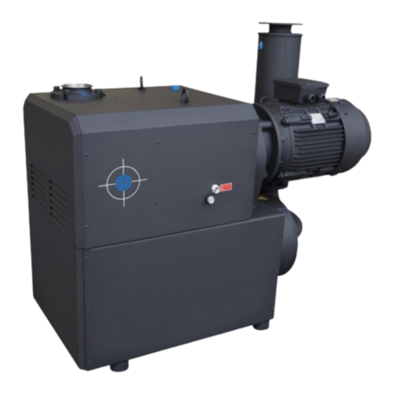
- Page 1 I.VA.CO. srl Installation And Operating Manual ICP SERIES VACUUM PUMP MODELS 255, 305, 415 & 515 www.ivaco.it 2.2017 (REV1)
-
Page 2: Table Of Contents
INSTALLATION & OPERATING MANUAL ICP SERIES CLAW COMPRESSOR ICP 255, 305, 405 & 515 Please read the manual before operating the compressor. TABLE OF CONTENTS 1.0 INSTALLATION 1.1 General description 1.2 Unpacking 1.3 Location 1.4 Power Requirements 1.5 Pressure Connections 1.6 Oil Filling on Gear box... -
Page 3: Installation
For a protection of overload, a pressure safety valve or regulating valve is installed in exhaust. The compressors are directly driven by a flanged motor via a coupling. The ICP Series compressors are identical in internal construction to ICV vacuum pump, but are outfitted with different inlet and outlet accessories to allow for operation as a compressor. -
Page 4: Pressure Connections
High Voltage Star Connection The motor must be connected according to the electrical codes through a fused switch in order to protect the motor against electrical or mechanical overload conditions. The overload of the motor starter must be set at a level equal to the full load motor current listed on the motor nameplate. -
Page 5: Safety
I.VA.CO. shall have no liability for any accident and failure arising from no compliance with instructions in this manual. 2.2 Warning labels and its explanation Following warning labels are shown and attached on ICP series compressors. 2.2.1 Read and Understand a manual: Read and understand operator’s manual before using this machine 2.2.2 Burn Hazard:... -
Page 6: Operation
To stop the compressor, turn off the power. 3.3 Operating Conditions and limits The ICP series are designed to run below set pressures according to the motor power for continuous operation. Operation over maximum pressure level may result in failure of and severe damage to the machine. -
Page 7: Inline (Inlet) Filter
4.1.2 Gear Oil Type and Quantity See section 1.5 - Oil Filling - for details on oil type and quantity 4.1.3 Oil Change Under normal ambient conditions with proper Gear Oil, it is recommended to change the oil every 10,000 operating hours. -
Page 8: Problem Solving
5.0 PROBLEM SOLVING 5.1 Problem Compressor does not reach capacity. 5.1.1 Possible Cause Inlet screen (mesh) of the inlet filter clogged with debris. Remedy : check inlet filter element and clean screen (mesh) by compressed air or wash it. 5.1.2 Possible Cause Pipe work is too long or small. -
Page 9: Technical Data
5.6 Problem Compressor is running too hot. 5.6.1 Possible Cause Not enough air ventilation to Compressor Remedy : Make certain a sufficient amount of fresh air is supplied to the Compressor. Dirty or Blocked Mesh Remedy : Check the flow of cooling air and clean the metal mesh of any debris blocking the air as necessary. - Page 10 ICP-255 "A" "B" 50Hz, 7.5Kw : 961mm 60Hz, 9.2Kw : 1,001mm 50Hz, 11Kw 1,171mm 379mm 60Hz, 15Kw 1,171mm 379mm 60Hz, 15Hp 1,139mm 389mm 60Hz, 20Hp 1,183mm 433mm 60Hz, 25Hp 1,239mm 468mm "B" "A"...
- Page 11 ICP - 305 "A" "B" 50Hz, 7.5Kw : 973mm 50Hz, 11Kw 973mm 379mm 50Hz, 15Kw 973mm 379mm 60Hz, 15Kw 973mm 379mm 60Hz, 18.5Kw : 973mm 379mm 60Hz, 20Hp : 1,195mm 433mm 60Hz, 25Hp : 1,251mm 468mm "B" "A"...
- Page 12 ASS'y DRAWING ICP-255 / 305 (IEC)
- Page 13 ASS'y DRAWING ICP-255 / 305 (NEMA)
- Page 14 ICP 255 / 305 PART LIST POS# Description Q'ty POS# Description Q'ty POS# Description Q'ty Gear Box Housing Inlet flange, Upper Housing, G 2" Elbow, inlet 2" Gear Box Cover (rear) Plug 1-1/2" Inlet screen (Conical ) Pump Housing Cover 1 (End Plate) Base O-Ring, Inlet Flange, upper part Fan Housing...
- Page 15 ICP - 405 Dimensions "A" "B" 50Hz, 11Kw : 1,274mm 50Hz, 15Kw : 1,274mm 60Hz, 15Kw : 1,274mm 50Hz, 18.5Kw : 1,274mm 60Hz, 18.5Kw : 1,274mm 50Hz, 22Kw : 1,340mm 346mm : 1,340mm 60Hz, 22Kw 346mm 60Hz, 30Kw : 1,395mm 514mm 60Hz, 20Hp : 1,286mm...
- Page 16 ICP - 515 Dimensions "A" "B" 50Hz, 15Kw : 1,289mm 50Hz, 18.5Kw : 1,289mm 60Hz, 18.5Kw : 1,289mm 50Hz, 22Kw : 1,355mm 346mm 50Hz, 30Kw : 1,410mm 514mm 60Hz, 30Kw : 1,410mm 514mm 60Hz, 37Kw : 1,410mm 514mm 60Hz, 25Hp : 1,302mm 60Hz, 40Hp : 1,406mm...
- Page 17 ASS'y DRAWING ICP-405 / 515 (IEC)
- Page 18 ASS'y DRAWING ICP-405 / 515 (NEMA)
- Page 19 ICP 405 / 515 PART LIST POS# Description Q'ty POS# Description Q'ty POS# Description Q'ty Gear Box Housing Elbow, inlet 2" Inlet Flang Gear Box Cover (rear) plug 1-1/2" Inlet screen (Conical ) Pump Housing Cover (End Plate) Base Gasket, Inlet Flange Fan Housing Bracket with Elbow Cover, Exhaust...
- Page 20 I.VA.CO. Italian Vacuum Compressors Via delle Brigole, 33 23877 Paderno d’Adda (LC) Italy +39 039 9281084 info@ivaco.it www.ivaco.it...
Need help?
Do you have a question about the ICP Series and is the answer not in the manual?
Questions and answers