
Subscribe to Our Youtube Channel
Related Manuals for Lennox EMEA MONOTOP R290


Summary of Contents for Lennox EMEA MONOTOP R290
- Page 1 INSTALLATION, USER AND MAINTENANCE MANUAL Refrigeration monoblock unit MONOTOP R290 N° IN00xxxxx-A 02.2022...
-
Page 3: Table Of Contents
INDEX PRODUCT SPECIFICATIONS ........................... 3 1.1. DESCRIPTION ..............................3 1.2. DESIGNATION ..............................4 1.3. OPERATING LIMITS ............................. 4 1.4. TECHNICAL CHARACTERISTICS AND DIMENSIONS ..................4 1.5. EQUIPMENT DESIGN ............................5 UNIT PREPARATION FOR USE ..........................5 2.1. TRANSPORT ................................. 5 2.2. -
Page 4: Product Specifications
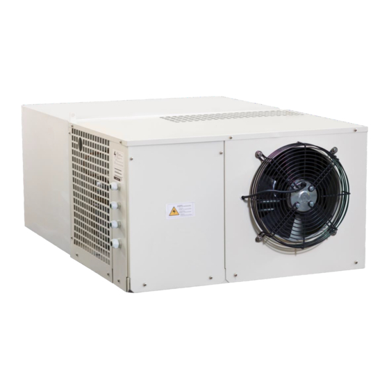
1. PRODUCT SPECIFICATIONS 1.1. DESCRIPTION MONOTOP commercial equipments are compact compression cooling units, air-cooled or water- cooled, for cold storage rooms which have a small volume and for use in medium and low temperatures, governed by an intelligent control. The power supply is single phase or three phases depending on the equipment. -
Page 5: Designation
1.1. 1.2. DESIGNATION MONOTO (A) MONOTO = Compact ceiling refrigeration (B) P = Positive range – N = Negative range (C) Model (D) P = R290 1.3. OPERATING LIMITS The MONOTOP units are designed for correct continuous functioning between the temperature limits shown in the following table. -
Page 6: Unit Preparation For Use
2. UNIT PREPARATION FOR USE 2.1. TRANSPORT The cooling unit must be handled and stored with care, in accordance with applicable regulations. Please also follow the following instructions: - Do not start up the unit until 6 hours have elapsed after transportation - The unit must be transported and handled in vertical position, protecting it against water and knocks - Never stack the units during transport without being well insured. -
Page 7: Important Safety Warnings
2.2. IMPORTANT SAFETY WARNINGS Below are some safety tips to be followed during the installation and use of the unit. • The unit must be installed in accordance with the diagrams and recommendations provided by the Manufacturer. • Damage due to improper connections is not covered. •... -
Page 8: Indications
2.3. INDICATIONS The manufacturer has applied the use of warning labels and the guidance given in the following summary table. 1) Product 2) Unit model 3) Unit serial number 4) Year of manufacture 5) Type of refrigerant 6) Amount of refrigerant 7) Weight of the unit 8) Tension 9) Maximum current of the unit... - Page 9 ! CUIDADO ¡ Peligro de electrocución. “CAUTION! Riskofelectricshock. Disconnectpowerbeforeservicingunit. !ATENTION¡ !KONTUZ¡ !KONTUZ¡ Salida / Output / Sortle principal.
-
Page 10: Installing The Unit
2.4. INSTALLING THE UNIT To guarantee correct functioning of the MONOTOP for optimising its electrical consumption per Kg of product stored and to prevent breakdown, it is vitally important that it is placed in a suitable location and properly used. The unit must be installed on a cold room for what has to be raised using appropriate means The unit has pull tabs for easy installation on the camera. -
Page 11: Compulsory Space To Be Left Around The Unit
2.5. COMPULSORY SPACE TO BE LEFT AROUND THE UNIT The unit’s location must allow access for the relevant technical and maintenance service to be carried out, in compliance with all the safety requirements applicable in the country. It must be installed in places where good ventilation and air circulation is guaranteed. It must have a minimum clearance of 0.3m. -
Page 12: Protective Devices And Safety Measures
2.7. PROTECTIVE DEVICES AND SAFETY MEASURES The manufacturer has provided the following safety protections: 1. The metal casing is bolted to the structure. 2. The fans are bolted to the metal structure. 3. The fan access is covered by a grille bolted in place. 4. -
Page 13: Operating Instructions
3. OPERATING INSTRUCTIONS 3.1. CONNECTING THE UNIT TO EXTERNAL POWER SOURCES CAUTION Before making the electrical connection, check that the mains voltage and frequency are as indicated on the unit label and that the current remains at a tolerance of +/- 10% with respect to the nominal value. -
Page 14: Cold Room Light
The temperature setting can be viewed by pressing the button and changed by pressing the buttons. To protect the compressor from successive start-up and stopping, the adjustment system includes an anti- short cycle timer. The unit automatically goes into defrost mode after a cooling cycle functioning time of 4 hours. The unit is supplied with the defrost mode controlled by the internal battery temperature. -
Page 15: Control Functions
3.6. CONTROL FUNCTIONS • To switch the unit on or off. - 2. press the button. “OFF” will appear for 5 s. • To view the maximum temperature set. - 1. press the button. 2. the value will appear on the screen together with the message “Hi”. 3. -
Page 16: Indicator Lights
3.7. INDICATOR LIGHTS Indicator State Meaning The compressor is functioning. Anti-short cycle safety device activated. Compressor indicator Voltage relay activated light Flashing High or low pressure switches open. Programming (flashing together with the fan indicator light). The fan is functioning. Fan indicator light Programming (flashing together with the Flashing... -
Page 17: Pal/Ca Alarm
3.10. PAL/CA ALARM Indicative of activation of digital input 7-8, means that it has been activated 2 times in 20 minutes. (Parameters Nps = 2 did = 20). Possible causes: PR Voltage Protector see "Network Protector States" on page 17-18. 2-Analyze electrically low pressure switch (PB), high pressure switch (PA). - Page 18 - Evaluate reading value Pb2, with chamber temperature close to the set point, this value must be less than Pb1. In case that PA is open, indicative of stop by high pressure, causes: - Error pressure switch or electrical connection pressure switch. - Condenser input temperature too high, lack of air renewal or near heat source.
-
Page 19: P1, P2, P3, P4 Alarm
Three-phase voltage protector ZHRV5-10 3.11. P1, P2, P3, P4 ALARM Indicative of non-detection of the probe in the analog input Possible causes: 1. Connection defective probe in the terminal or corresponding terminal according to alarm. Detect bad contact Example; Alarm P1, check the connection as well as the contact of the cable tips that enters terminals 01-02. If the alarm is maintained, change connection 01 through connection 03, if alarm P1 disappears and alarm P2 appears, it means deteriorated probe P1, replace probe P1, and return to original connection, P1 terminal 01, P2 terminal 03. -
Page 20: Da Alarm
3.12. dA ALARM Indicative of analogue input micro door open. Possible causes: 1- Analogue input terminals 09-08, must be closed, check ferrules and connection, possible bad contact. 2- The micro door cable bridge has been cut. The cable for micro door supplied to be bridged, is connected to each other. -
Page 21: Parameter List
3.14. PARAMETER LIST Code Description Cool. Freez. Temperature setting 2 ºC -18 ºC Indicates the difference with respect to the temperature setting above which the compressor will start up Thermostat probe calibration (1) Probe 2 presence (the probe is connected) Indicates the time of the anti-short cycle in minutes, the minimum time 3 min... -
Page 22: Starting Up The Unit
3.16. STARTING UP THE UNIT Before starting up the cooling unit, the following operations must be performed: Plug the unit into the mains. The display will switch on and the word OFF will appear. If warm-up of the unit is required, it must remain in this state for at least three hours. If the unit has a voltage monitor incorporated, it must remain turned to OFF for at least 7 minutes, so that the monitor can run the calculation phase. -
Page 23: Ordinary Maintenance
4.2. ORDINARY MAINTENANCE To always obtain a good functioning of the equipment, it is necessary to periodically: -Verify weekly that the evaporator is clean, without accumulation of ice. -Monthly (at least) perform a cleaning of the condenser (the periodicity of this cleaning depends mainly on the environment where said unit has been installed). -
Page 24: Technical Problems
4.5. TECHNICAL PROBLEMS The following problems may occur during unit functioning: 1. Blocked compressor. There is a protective device which starts up whenever the maximum permitted temperature for the coils of the compressor’s electric motor is exceeded. This may happen if: - The space the unit is located in is not sufficiently ventilated. -
Page 25: Failure Analysis
4.6. FAILURE ANALYSIS Symptom Cause Solution Very high a) Excess load a) Collect refrigerant b) High cold room temperature b) Check for overheating evaporator c) Compressor air intake not c) Check the state of the compressor and pressure with correctly sealed replace it respect to air input. -
Page 26: How To Order Spare Parts
4.7. HOW TO ORDER SPARE PARTS If you need to order any spares, please state the serial number figuring on the unit label. WARNING Components must only be replaced by authorised, qualified staff. 4.8. SCRAPPING THE UNIT If the unit is to be scrapped, its components must not be abandoned in the environment; they must be disposed of through companies authorised to collect and recycle special waste, in accordance with the laws applicable in the country in which the unit is used. - Page 28 LENNOX EMEA reserves itself the right to make changes at any time without preliminary notice. www.lennoxemea.com...
Need help?
Do you have a question about the MONOTOP R290 and is the answer not in the manual?
Questions and answers