
Related Manuals for MBM A5A20

Summary of Contents for MBM A5A20
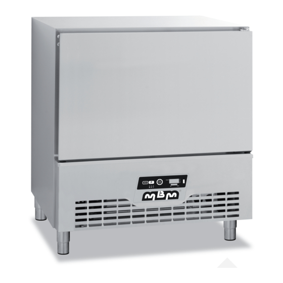
- Page 1 BLAST CHILLERS AND FREEZERS INSTALLATION MANUAL n° 6CE648070NI–0712 INSTALLATION MANUAL BLAST CHILLERS AND FREEZERS Models: 5 Levels 12/6 and 20/10 kg 10 Levels 35/15 and 45/20 kg 13 Levels 60/25 and 80/40 kg FORM049C1/3...
- Page 2 IMPORTANT RECOMMENDATIONS The installation of this equipment should be entrusted to technicians approved by the vendor and in compliance with standards and rules in force. Before installing the unit ensure that the circulation and volume of air are sufficient to allow normal cooling of the condenser and compressor. Avoid installing the cabinet near major sources of heat or in direct sunlight.
-
Page 3: Table Of Contents
BLAST CHILLERS AND FREEZERS INSTALLATION MANUAL n° 6CE648070NI–0712 TABLE OF CONTENTS BLAST CHILLERS AND FREEZERS Models: 5 Levels 12/6 and 20/10 kg 10 Levels 35/15 and 45/20 kg 13 Levels 60/25 and 80/40 kg 1. Technical Characteristics 1.1 5-level 12/6 and 20/10 1.2 10-level 35/15 and 45/20 1.3 13-level 60/25 and 80/40 2. -
Page 4: Technical Characteristics
BLAST CHILLERS AND FREEZERS INSTALLATION MANUAL n° 6CE648070NI–0712 1. TECHNICAL CHARACTERISTIC 1.1 5-level 12/6 and 20/10 Dimensions (mm) Height Width Depth Outer Inner Weight (Kg) 12/6 20/10 Gross Electric characteristics Voltage 1~230V Frequency 50 Hz Protection AM 4 Maximum power 600 W 900 W Refrigeration characteristics... -
Page 5: 10-Level 35/15 And
BLAST CHILLERS AND FREEZERS INSTALLATION MANUAL n° 6CE648070NI–0712 1.2 10-level 35/15 and 45/20 Dimensions (mm) Height Width Depth Outer 1550 Inner Weight (Kg) 35/15 45/20 Gross Electric characteristics Voltage 1~230V Frequency 50 Hz Protection AM 8 Maximum power 1600 W 1800 W Refrigeration characteristics 2080 à... -
Page 6: 13-Level 60/25 And
BLAST CHILLERS AND FREEZERS INSTALLATION MANUAL n° 6CE648070NI–0712 1.3 13-level 60/25 and 80/40 Dimensions (mm) Height Largeur Profond Outer 1825 Inner 1075 Weight (Kg) 60/25 80/40 Gross Electric characteristics Voltage 1~230V 400V 3N~ Frequency 50 Hz Protection AM 10 Maximum power 2500 W 2500 W Refrigeration characteristics... -
Page 7: Nameplate
BLAST CHILLERS AND FREEZERS INSTALLATION MANUAL n° 6CE648070NI–0712 2. NAMEPLATE The nameplate is to be found fixed on the bottom right of the cabinet. For all correspondence relating to your equipment remember: - The unit code (Type) - The serial number (N° SERIE) - The date (Date) The main characteristics are repeated on a label fixed to the left hand internal panel. -
Page 8: Connections
BLAST CHILLERS AND FREEZERS INSTALLATION MANUAL n° 6CE648070NI–0712 Lift the appliance to pull out its wooden pallet and install the assembly. Level the equipment with the screw jacks. Note that door alignment may be adjusted by adjusting the screw jacks of the front legs. Install the drip tray. - Page 9 BLAST CHILLERS AND FREEZERS INSTALLATION MANUAL n° 6CE648070NI–0712 3.5 KIT ASSEMBLY 3.5.1 HACCP SOCKET KIT 1°) Replace the 1-pin probe mounted as standard by the 2-pin probe supplied with the kit by connecting: . both white cables instead the white and red cables of the 1-pin standard probe (terminals 31 &...
-
Page 10: Commissioning
BLAST CHILLERS AND FREEZERS INSTALLATION MANUAL n° 6CE648070NI–0712 4. COMMISSIONING 4.1 GENERAL REQUIREMENTS Check that no foreign body obstructs the evaporator and condenser ventilators. If the appliance was laid flat during transportation, wait 24 hours before putting it in service so as to allow oil to return from the refrigerating circuit to the compressor pan (housing). - Page 11 BLAST CHILLERS AND FREEZERS INSTALLATION MANUAL n° 6CE648070NI–0712 4.3.3 PARAMETRES Description Notes Temperature scale 1=°C, 2=°F Ambient probe calibration °K Skewer probe activation 0=NO, 1=YES Skewer probe calibration °K T2=1 Action digital entry 1 0=NON, 1=DOOR Polarity Digital Entry 1 DI1 = 1 0=NO, 1=NF Action Digital Entry 2...
- Page 12 BLAST CHILLERS AND FREEZERS INSTALLATION MANUAL n° 6CE648070NI–0712 setpoint of ambient probe for Setpoint refrigeration conservation °C conservation 0=NO, 1=YES Selection of soft chill cycle function activated SCE=1 setpoint of ambient probe during Setpoint Soft chill ambient probe °C refrigeration cycle 0=NO, 1=YES Selection of freezing cycle activated setpoint of ambient probe for...
-
Page 13: Electric Diagrams
BLAST CHILLERS AND FREEZERS INSTALLATION MANUAL n° 6CE648070NI–0712 5. ELECTRIC DIAGRAMS 5.1 MODELS 12/6, 20/10, 35/15 and 45/20 SdA : Ambient probe SdP : Skewer probe Black Cp : Compressor Vc : Condenser Ventilator Blue Ve : Evaporator ventilator Brown Cd : Evaporator ventilator condenser Rev :... - Page 14 BLAST CHILLERS AND FREEZERS INSTALLATION MANUAL n° 6CE648070NI–0712 5.2 MODEL 60/25 SdA : Ambient probe SdP : Skewer prober Cp : Compressor Black Vc : Condenser ventilator Ve : Evaporator ventilator Blue Cd : Evaporator ventilator condenser Brown HP : Pressure gauge Rc : Pan (housing) resistance...
- Page 15 BLAST CHILLERS AND FREEZERS INSTALLATION MANUAL n° 6CE648070NI–0712 5.3 MODEL 80/40 SdA : Ambient probe SdP : Skewer prober Black Cp : Compressor Vc : Condenser ventilator Blue Ve : Evaporator ventilator Brown Cd : Evaporator ventilator condenser HP : Pressure gauge Rc : Pan (housing) resistance...
Need help?
Do you have a question about the A5A20 and is the answer not in the manual?
Questions and answers