Table of Contents
Advertisement
Quick Links
Advertisement
Table of Contents

Related Manuals for Hirose HRS HT603/TM21P-88P


Summary of Contents for Hirose HRS HT603/TM21P-88P
- Page 1 First edition MANUAL INSULATION DISPLACEMENT TOOL INSTRUCTION MANUAL CAUTION : Be sure to read this Instruction Manual carefully before using it to secure safety in operation. In addition, save this Instruction Manual so that it is available whenever necessary for review.
- Page 3 This tool shall only be used for its originally intended purpose while following the instructions specified in this Instruction Manual. Hirose assumes no responsibility for any misuse of the tool other than the intended use. Modifications to this tool is prohibited. We assume no responsibility for accidents resulting from modifications.
-
Page 4: Table Of Contents
CONTENTS CHAPTER 1 SPECIFICATIONS AND CONFIGURATION ....1-1. Model ..............................1-2. Specifications ............................ 1-3. Shape of tool and names of components ..................CHAPTER 2 OPERATING PROCEDURE ..........2-1. Cable end finish ..........................2-2. Installing crimper and anvil ......................2-3. -
Page 5: Specifications
第1章 仕様と構成/CHAPTER 1 SPECIFICATIONS AND CONFIGURATION 1-1. 型式/Model 製品番号/Product No. HRS.No. CL902-2532-0 HT603/TM21P-88P 1-2. 仕様/Specifications 項目/Item 仕様/Specification 長さ 236㎜ × 幅 71㎜ × 厚さ 21.5㎜ 外形寸法/External dimensions Length 236 mm × Width 71 mm × Thickness 21.5 mm 重量/Weight 1.0kg TM21P-88P(CL222-2862-9)... - Page 6 TM31P-TM-88P, TM36P-TM-88P 適合ケーブル仕様/Applicable cable specifications 導体 AWG#24~#27 より線 AWG #24 to #27 stranded wire Conductor シース Sheath 編組シールド Braid shield 絶縁体外径 (φ0.9㎜ ~ φ1.0㎜) Insulator external (ø 0.9 mm to ø 1.0 mm) diameter 絶縁体 Insulator すずめっき軟銅線編組シールド、 遮蔽体 ラミネートテープ 電線シールド Wires shield Shield material...
-
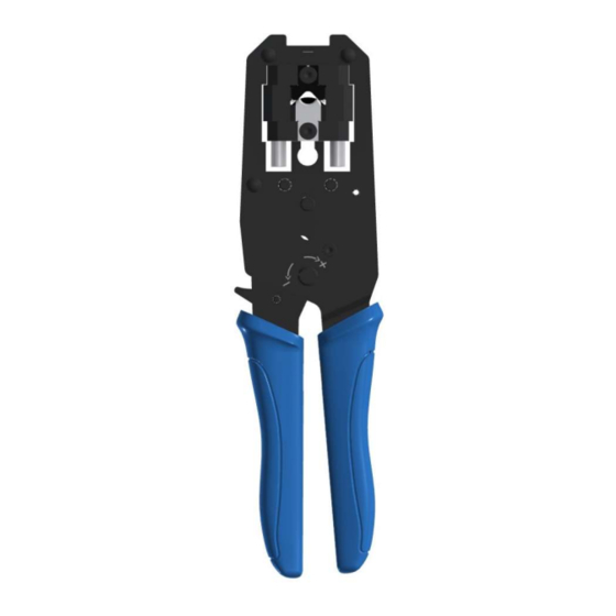
Page 7: Shape Of Tool And Names Of Components
Shape of tool and names of components Crimper fixing screw Connector holder Insulation Crimper displacement punch Anvil HRS marking Anvil fixing screw Product name marking... -
Page 8: Chapter 2 Operating Procedure
CHAPTER 2 OPERATING PROCEDURE Cable end finish Shield Sheath Drain wire Peel the cable sheath by approximately 30 mm. [Caution] When peeling the sheath, be careful not to damage the inside signal wire. When the wire is damaged, defective compression proofing or the like will be caused. - Page 9 Drain wire Slacken the twist of the twist pair up to the end of the cable sheath and stretch to correct the way. At this time, bend the drain wire on the outside of the cable. [Caution] When the correction of the twist of the twist pair is not sufficient, the work of the post-process will be difficult.
- Page 10 Cut and arrange the top ends of the cable contact wires Cut and arrange with nippers or the like so that the guide plate can be the top ends. easily placed. Guide plate 3 to 5 mm Deformation of guide plate Insert the guide plate into the position of 3 to 5 mm from the end of the sheath.
- Page 11 End of sheath Turn the copper tape of approximately 12.7 mm wide Copper tape once around the sheath of the cable. For the length of the copper tape, make as the standard Glue side the length that the external diameter is approximately 6.8 mm in the state that it is turned around the cable.
- Page 12 Insert the cable from the upper aslant direction so that it does not come in contact with the cable clamp section of the connector main unit. When the top end of the guide plate has entered in the connector main unit, insert it to the position where the top end section of the cable comes in contact with the inside of the connector main unit.
-
Page 13: Installing Crimper And Anvil
2-2. クリンパ・アンビルの取り付け/Installing crimper and anvil ① 本工具にはクリンパ・アンビルが2個ずつ添付さ れています。 各々に線が1本、または2本付いています。 下表に従って、正しい組み合わせを選んでくださ 識別線 い。 Discrimination line ① Two pieces each of crimper and anvil are provided with this tool. One or two wires are provided with each. Select the proper combination following the table below. 識別線... -
Page 14: Wire Connecting Operation
Wire connecting operation Open the handle of HT603/TM-21P-88P to the maximum after closing once and releasing the ratchet. Insert the connector into the insertion opening of the tool and hold the handle while pushing the cable in the direction of the arrow. [Caution] When inserting, be careful not to mistake the direction of the connector. -
Page 15: Quality Standard
Quality standard Top end position of guide plate Top end of contact wire comes in contact with wall. Confirm that the connector after the insulation displacement satisfies the standard below. The top end of the contact wire comes in contact with the Bending angle wall of the plug. -
Page 16: Chapter 3 Maintenance And Inspection
CHAPTER 3 MAINTENANCE AND INSPECTION Matters that demand special attention when handling Never apply shocks such as tapping, dropping the tool from a high place, etc. Never perform insulation displacement of anything other than the applicable connector and applicable cable described in this Manual. - Page 19 First edition CAUTION No part of this manual may be reproduced without the permission of Hirose Electric Co., Ltd. Description in this manual is subject to change without notice. This Instruction Manual has been prepared for clarify. Should you find any unclear portion, error, or omission, please, for the safety of other, contact our Marketing Department.
- Page 20 6-3, NAKAGAWACHUO 2-CHOME, TSUZUKI-KU, YOKOHAMA-SHI, KANAGAWA 224-8540, JAPAN https://www.hirose.com 21.04 Printed in Japan...
Need help?
Do you have a question about the HRS HT603/TM21P-88P and is the answer not in the manual?
Questions and answers