
Related Manuals for QTech QSRV-26 Series

Summary of Contents for QTech QSRV-26 Series
- Page 1 РУКОВОДСТВО ПОЛЬЗОВАТЕЛЯ QTECH QSRV-26xxxx platform 2U manual server barebones www.qtech.ru...
-
Page 2: Preface
This chapter mainly introduces how to set up RAID. Chapter 7 IPMI Rapid Deployment This chapter mainly describes how to quickly deploy IPMI. Chapter 8 Product Technical Specifications This chapter focuses on the main technical specifications of Purley 2U dual-socket cabinet server products. www.qtech.ru... -
Page 3: Statement
QTECH), no copying, copying, or excerpting is allowed. , Re-issuance, or other use. Disclaimer QTECH provides this user manual "as is". Within the scope of the law, it does not provide any express or implied guarantees and guarantees, including but not limited to... - Page 4 NC Pin Empty pin Extend Debug Port, Intel®CPU debugging interface Abbreviations Explain the abbreviations used in this article, and provide the full English name and Chinese explanation of each abbreviation, as shown in the following table: www.qtech.ru...
- Page 5 Motherboard Interface Board Motherboard adapter board/side board Backplane Backplane Power Distribution Board Power distribution board Fan Interface Board Fan adapter board PCIE Peripheral Component High-speed serial computer expansion Interconnect bus standard Express Universal Serial Bus Universal Serial Bus Firmware firmware www.qtech.ru...
- Page 6 Cubic Feet Per Minute Cubic feet per minute Revolution Per Minute Symbol convention: Note: It is used to transmit equipment or environmental safety warning messages. If not avoided, it may cause equipment replacement, data loss, equipment performance degradation or other unpredictable results. www.qtech.ru...
- Page 7 Hollow arrow: represents the next action or result. Dark blue rotating arrow 1: represents the action of turning the screw clockwise or pulling out. Dark blue rotating arrow 2: represents the action of turning the screw counterclockwise or buckling inward www.qtech.ru...
-
Page 8: Table Of Contents
2.4.8 System fan 3 INSTALLING SYSTEM COMPONENTS 3.1 CPU installation 3.2 Radiator installation 3.3 Memory installation 3.4 Hard disk installation 3.5 Front hard disk backplane installation. 3.6 M.2 SSD installation 3.7 PCI-E module installation 3.8 Rear hard disk module backplane installation www.qtech.ru... -
Page 9: Statement
5.2.13 Network Stack Configuration 5.2.14 iSCSI Configuration 5.2.15 Platform Configuration menu 5.2.16 PCH SATA Configuration 5.2.17 PCH sSATA Configuration 5.2.18 USB Configuration 5.2.19 Miscellaneous Configuration 5.2.20 Server ME Configuration 5.2.21 Runtime Error Logging 5.2.22 Socket Configuration menu 5.2.23 Processor Configuration www.qtech.ru... -
Page 10: Statement
6.1.3 Delete RAID: 6.2 LSI 9361-8i group RAID 6.2.1 Configure RAID in UEFI boot mode 6.2.2 Create RAID: 6.2.3 Configure hot spare disk: 6.2.4 Delete RAID: 6.2.5 Erase disk data: 6.2.6 Migrate RAID level: 6.2.7 Clear disk RAID information: www.qtech.ru... -
Page 11: Statement
7.2.4 Introduction to KVM remote management 7.2.5 KVM page introduction 7.2.6 Remote control quick operation 7.2.7 Introduction to SOL 7.3 Other ways to connect to IPMI 7.3.1 IPMI driver 7.3.2 IPMI tools and other open source software 8 PRODUCT TECHNICAL SPECIFICATIONS 8.1 Technical specifications www.qtech.ru... -
Page 12: Security Statement
If you need twisting table cable wiring, please contact QTECH to provide suggestions. Please use a three-core power cord and socket with grounding protection. Improper grounding may cause leakage, burns, explosions and even personal injury. -
Page 13: Product Name And Content Identification Table Of Toxic And Hazardous Substances Or Elements
Please keep the environment clean and avoid dust. The working environment temperature of the equipment is 10℃~35℃, and the humidity is 35%~80%. Users are requested to back up important data in time. QTECH is not responsible for data loss caused by any circumstances. - Page 14 Руководство пользователя 1. Security Statement motors, etc.) Printed Circuit Components- PCA* Cable/wire/con nector Hard disk drive Table 1-1 www.qtech.ru...
- Page 15 Electrical Products". But it complies with the EU RoHS directive (including its exemption clauses). Note: This table shows the status of toxic and hazardous substances contained in all components that may be used in QTECH server, storage and workstation products. www.qtech.ru...
-
Page 16: Warning Notice
When the maximum dew point is 33°C storage (91°F), the relative humidity is 5% to 95%. The air must never condense. When the maximum dew point is 26°C Continuous operating (78.8°F), the relative humidity is 10% to humidity percentage range Table 1-3 www.qtech.ru... -
Page 17: Other Important Description
❖ When the server fails, please first check the "Troubleshooting" section of this manual to determine and eliminate common failures. If you are not sure of the cause of the failure, please contact the technical support department of QTECH for help. -
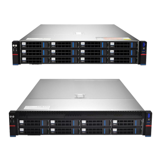
Page 18: Product Introduction
Purley 2U dual-channel L-type server is a new generation of 2U dual-channel cabinet server with a wide range of uses that QTECH has launched for the needs of the Internet, IDC (Internet Data Center), cloud computing, enterprise market and telecom business applications. -
Page 19: System Structure
6 Two channels, each channel supports 2 DIMMs; two CPUs support a total of 24 DDR4 slots; supports a single capacity of 8GB, 16GB, 32GB, 64GB, 128GB. The main board features are as follows: ❖ The CPU adopts the first and second generation Intel® Xeon® scalable processors, LGA3647 socket, TDP power consumption 205W; www.qtech.ru... - Page 20 ❖ The BMC chip in this single board uses ASPEED's AST2500 control chip to Do IPMI remote management. VGA output port, dedicated Gigabit RJ45 management network port, and connected to PCH through RMII/NCSI. The main board block diagram of the system architecture is as follows: Figure 2-1 www.qtech.ru...
-
Page 21: System Model Specification Introduction
Support DDR4 LRDIMM/RDIMM/NV-DIMM (system) ECC memory Memory frequency support 2133/2400/2666/2933MHz A single CPU supports 6 DDR4 Channels, each Channel has 2 slots, CPU0/CPU1 totals 24 DDR4 slots Support a single capacity of 8GB, 16GB, 32GB, 64GB, 128G www.qtech.ru... - Page 22 Data network port, 1 DB-9 COM port manageme onboard iBMC management module supports IPMI, SOL, KVM Over IP, Management features such as virtual media System fan 4 8038 brand fans (optional 4 8056 brand fans) power Standard platinum 550W, optional 800W, www.qtech.ru...
- Page 23 Support DDR4 LRDIMM/RDIMM/NV-DIMM ECC memory (system) Memory frequency support 2133/2400/2666/2933MHz A single CPU supports 6 DDR4 Channels, each Channel has 2 slots, CPU0/CPU1 totals 24 DDR4 slots Support a single capacity of 8GB, 16GB, 32GB, 64GB, 128G www.qtech.ru...
- Page 24 IPMI, SOL, KVM Over IP, and virtual media System fan 4 8038 brand fans (optional 4 8056 brand fans) Standard platinum 550W, optional 800W, Power supply 1200W, 1600W hot-swappable redundant power supply (CRPS) Dimensions 2U cabinet type, 748x433.4x87.6mm www.qtech.ru...
-
Page 25: System Component Introduction
Serial name number number Built-in DVD drive USB3.0 interface VGA interface 3.5 inch hard drive Table 1- 7 ❖ 2U12 disk bay 3.5 inch disk model Figure 2-5 Serial name Serial name number number hard disk USB3.0 interface www.qtech.ru... - Page 26 USB device, please make sure that the USB device is in good condition, otherwise it may cause the server to work abnormal. Table 1- 9 ❖ Description of front panel indicators and buttons Figure 2- 6 www.qtech.ru...
- Page 27 OS will shut down normally. Press and hold this button for 6 seconds in the power-on state to force the server to power off. Short press the button when it is to be powered on, you can Turn on. www.qtech.ru...
- Page 28 Network port card. Green (steady light): connection indicates that the network port status is connected normally. Off: indicator indicates that the network port is not in use or is faulty. Note: Corresponding to two 1GE network ports on the motherboard. www.qtech.ru...
-
Page 29: Rear Panel Components
Figure 2-7 Serial number name Serial number name Rise module USB 3.0 interface Hard Disk OCP3.0 interface Module Management Power module 1 network port Power module interface interface RJ45 Gigabit Power module 2 Ethernet port COM port Power module interface www.qtech.ru... - Page 30 You can choose the number of module power supplies according to your 1 or 2 actual needs, but you must ensure interface that the rated power of the power supply is large It is the rated power of the whole machine. www.qtech.ru...
- Page 31 ❖ Description of indicators and buttons on the rear panel Figure 2-8 Serial number name Serial number name Connection Data transmission status status indicator indicator Data Power module indicator transmission status indicator Connection Power module indicator status indicator Table 1-14 Indicator State description light/button www.qtech.ru...
-
Page 32: Motherboard Components
Data Yellow (flashing): indicates that data is being transmission transmitted. status Off: No data is being transmitted. indicator Indicator light Table 1-15 2.4.3 Motherboard components ❖ All models share motherboard components, and the interface description is as follows www.qtech.ru... - Page 33 Руководство пользователя 2. Product Introduction Figure 2-9 www.qtech.ru...
-
Page 34: Hard Disk Backplane Assembly
1, 2, 3, 4 Temperature For 12G/b SAS or 6G/b SATA control Number transmission. socket 5, 6, 7 Power Backplane power transmission connector connector for 12V power supply Transmission. EXPANDER PM8043 SXP 24Sx12G chip 24-port 12G SAS Expander www.qtech.ru... - Page 35 ❖ 2U8 expansion backplane as shown TOP noodles Figure 2-12 Serial description Features number Maximum support 12G/b SAS hard disk; SAS0~7 SAS/SATA hard disk connector Maximum support 6G/b SATA hard disk; Supports swap SAS/SATA hard disks. Table 1- 18 Bottom surface www.qtech.ru...
- Page 36 For 4pin fan interface fan socket Table 1- 19 ❖ SAS/SATA backplane as shown TOP noodles Figure 2- 14 Serial description Features number Maximum support 12G/b SAS hard disk; SAS/SATA connector Maximum support 6G/b SATA hard disk; Supports swap SAS/SATA hard disks. www.qtech.ru...
- Page 37 SATA disk signal line interface SATA interface For I2C signal interface interface SGPIO Used hard disk lighting positioning fault signal indication Features. Power Backplane power transmission connecto connector power transmission lose Table 1- 21 ❖ U.2 backplane as shown www.qtech.ru...
- Page 38 Руководство пользователя 2. Product Introduction TOP noodles Figure 2-16 Serial description Features number Support PCIe×4 U.2 interface, SFF-8639 connector used to connect NVME SSD Table 1-22 Bottom surface Figure 2-17 Serial description Features number www.qtech.ru...
- Page 39 Power outlet 4 Pin power socket, used to dock PSU or Docking MB 4 Pin plug to power the board Table 1-23 Figure 2- 18 Serial description Features number PCIE 3.0 X8 Used for PCIe 3.0 X8 devices. Slot www.qtech.ru...
- Page 40 PCIE 3.0 Used for PCIe 3.0 X16 devices. Slot RISER Riser card power transmission POWER connector for 12V power supply Transmission PCIE For QTECH G3DCL motherboard specification PCIe X16 X8 gold interface finger PCIE For QTECH G3DCL motherboard specification PCIe X16 X8...
- Page 41 Руководство пользователя 2. Product Introduction PCIE QTECH G3DCL gold finger motherboard PCIe X16 X8 interface PCIE X8 gold QTECH G3DCL finger motherboard PCIe X16 X8 interface Table 1-25 Figure 2-20 Serial description Features number PCIE Used for PCIe 3.0 X16 devices.
-
Page 42: Dimm Slot Location
12 DDR4 Channels, 24 DDR4 slots (when only one memory is inserted, the plastic color of the slot on the slot board in the red box in the figure below is preferred) , Supports DDR4 ECC RDIMMs/LRDIMMs server memory, memory frequency supports 2133/2400/2666/2933MHz; the location is shown in the figure below: www.qtech.ru... -
Page 43: Hard Disk Label
2. Product Introduction Figure 2-22 2.4.6 Hard disk label ❖ 2U8 disk bay 3.5 inch disk model Figure 2- 23 ❖ 2U12 disk bay 3.5 inch disk model Figure 2-24 2.4.7 Hard Disk Indicator Fault LED StatusLED Act LED www.qtech.ru... -
Page 44: System Fan
Chang Liang Flashing reconstruct 1Hz/sec Table 1-28 2.4.8 System fan The server supports variable fan speeds. Generally, the fan rotates at the lowest speed. If the server temperature rises, the fan will increase the speed to cool down. Figure 2-27 www.qtech.ru... -
Page 45: Installing System Components
(As shown below) 1. Apply approximately 0.4ml thermal grease on the CPU and smooth it evenly. 2. Align the A1 corner (triangular mark) and buckle the CPU on the heat sink. Figure 3-3 Figure 3-4 www.qtech.ru... -
Page 46: Radiator Installation
(As shown below) Note: The pins on the motherboard are extremely fragile and easily damaged. To avoid damage to the motherboard, do not touch the processor or processor socket contacts. Figure 3-4 3.3 Memory installation www.qtech.ru... - Page 47 DIMME1, E2, DIMMF1, F2, DIMMG1, G2 and DIMMH1, H2, Note that the notch of the memory is consistent with the notch of the DIMM slot, and each DIMM module is vertically snapped in place to prevent incorrect installation. Figure 3-5 Figure 3- 6 Figure 3-7 www.qtech.ru...
-
Page 48: Hard Disk Installation
Figure 3-8 Figure 3-9 ❖ Install 2.5 inch hard drive 1. Place the hard drive in the tray 2. 4 countersunk screws at the bottom to lock the hard drive (the screw heads protrude from the bottom of the tray) www.qtech.ru... - Page 49 1. With the hard drive wrench open, push it into the chassis 2. When the hard disk golden finger touches the backplane device, turn the wrench in the direction of the arrow 3. Schematic diagram of hard disk installation in place www.qtech.ru...
-
Page 50: Front Hard Disk Backplane Installation
2. After the hard disk backplane is pushed into place, press the backplane down until the gourd nails and hanging holes on both sides are all in place 3. Turn over the fixing parts on the left and right sides of the hard disk backplane and lay the fixing parts flat. Figure 3-13 www.qtech.ru... - Page 51 Руководство пользователя 3. Installing System Components Figure 3-14 Figure 3-15 www.qtech.ru...
-
Page 52: Ssd Installation
Step 2: install M.2 card 1. Insert the M.2 card connector end into the motherboard connector as shown in the figure. 2. Press the other end of the M.2 card to the plane of the positioning stud in step 1. www.qtech.ru... -
Page 53: Pci-E Module Installation
Step 3: Install the fixing screws of the M.2 card. Figure 3- 18 3.7 PCI-E module installation Riser1-3 module installation steps: the rear window PCIE components, vertically downward-align the PCIE slot, align the positioning holes, and place it flush with the rear window. www.qtech.ru... -
Page 54: Rear Hard Disk Module Backplane Installation
2. Align the nail holes of the hard disk backplane with the nails of the hard disk module bracket and push it forward, and then place it down in place, release the hard disk limit shrapnel, and the shrapnel automatically springs back to the original position; www.qtech.ru... -
Page 55: Rear Hard Disk Module Installation
3.9 Rear hard disk module installation ❖ Rear 3.5 inch HDD tray installation Step 1. Place the HDD tray vertically downward and flush with the rear window Step 2. Fix the rear HDD tray component Step 3. Lock a captive screw www.qtech.ru... - Page 56 ❖ Rear 2.5 inch HDD tray installation 1. Place vertically downward, aiming at the guide pin at the lower end 2. After placing it flat, push it to the end in the direction of the arrow, 3. Lock the captive screws www.qtech.ru...
- Page 57 Руководство пользователя 3. Installing System Components Figure 3-25 Figure 3-26 www.qtech.ru...
-
Page 58: Power Supply Module Installation
3.10 Power supply module installation Step: Push the power supply in the direction of the arrow to the end, and the shrapnel wrench on the right makes a clicking sound, indicating that it is installed in place; Figure 3-27 Figure 3-28 www.qtech.ru... -
Page 59: Pci-E Expansion Card Installation
3.11 PCI-E expansion card installation Steps: install PCIE card 1. Install the PCIE card in the direction indicated in the figure 2. Rotate the PCIE card lock 3. Follow the arrow scheme to lock the PCIE card lock Figure 3- 29 www.qtech.ru... - Page 60 Руководство пользователя 3. Installing System Components Figure 3-30 Figure 3-31 www.qtech.ru...
-
Page 61: Fan Module Installation
Руководство пользователя 3. Installing System Components 3.12 Fan module installation Steps: The fan module is placed vertically downward in the direction of the arrow (note the direction of the fan module). Figure 3-32 Figure 3-33 www.qtech.ru... -
Page 62: Installation Of Air Duct
3. Installing System Components 3.13 Installation of air duct Steps: align the air baffle module with the hanging points on the left and right sides and place it vertically downward-the height is lower than the height of the cabinet Figure 3- 34 www.qtech.ru... -
Page 63: Cd-Rom Installation
1. The optical drive is as shown in Figure 3-34: Figure 3-35 2. Align the opening of the optical drive on the chassis, and push the optical drive in the direction of the arrow until the fixing part is automatically locked. Figure 3- 36 www.qtech.ru... - Page 64 Руководство пользователя 3. Installing System Components Figure 3-37 www.qtech.ru...
-
Page 65: Installation Of The Upper Cover Of The Chassis
Step 1: Install the back cover of the chassis 1. Align the top cover with the opening position of the box and place it down 2. Rotate the upper cover lock in the direction of the arrow to lock it in place Figure 3-38 Figure 3-39 www.qtech.ru... -
Page 66: System Cabinet Installation
Руководство пользователя 4. System cabinet Installation 4 SYSTEM CABINET INSTALLATION 4.1 Rail installation Step 1. Prepare two sliding rail frames and draw out the inner rail. Figure 4-1 Step 2. Fix the inner rails on both sides of the chassis. www.qtech.ru... - Page 67 Руководство пользователя 4. System cabinet Installation Figure 4-2 www.qtech.ru...
-
Page 68: Install The Outer Rail To Cabinet
Step 3. Install the outer rail on the cabinet bracket and tighten the screws. Note: When installing the guide rail, you need to align the U mark, and install it in place with a snapping sound. Use M5 screws to secure it. Figure 4-3 www.qtech.ru... -
Page 69: Install Server To Cabinet
Step 5. When the chassis is pushed forward and cannot slide, the screws are installed firmly. Note: When the equipment is maintained, it is necessary to loosen the panel screws and gently pull the chassis. Do not push and pull the chassis at will, so as not to damage the equipment. www.qtech.ru... - Page 70 Руководство пользователя 4. System cabinet Installation Figure 4-5 www.qtech.ru...
-
Page 71: Bios Parameter Setting Description
5.2 Setup menu parameter description 5.2.1 Navigation key description →←: Menu switch (Select Screen) ↑↓: Select Item Enter: OK (Select) +/-: Change Opt. (Change Opt.) General Help Previous Values Optimized Defaults Save changes and restart the system (Save & Reset) ESC: Exit www.qtech.ru... -
Page 72: Main Menu Description
5.2.2.5 CPLD Name: Display the CPLD name information of the board. 5.2.2.6 CPLD Version: Display the CPLD version information of the board. 5.2.2.7 Build Date and Time: Display the compilation date and time of the CPLD of the board. www.qtech.ru... - Page 73 "hour:minute:second". Press "Enter" to switch between hour, minute, and second. You can change the value in the following ways: ❖ Press "+": the value increases by 1. ❖ Press "-": the value decreases by 1. ❖ Press the number keys: directly change the value. www.qtech.ru...
-
Page 74: Advanced Menu Description
Руководство пользователя 5. BIOS parameter setting description 5.2.3 Advanced menu description The Advanced interface contains advanced configuration items of the BIOS system. Figure 5-2 www.qtech.ru... - Page 75 PCI Subsystem Settings. ❖ CSM Configuration CSM configuration. ❖ NVMe Configuration NVMe configuration. ❖ Network Stack Configuration Network Stack Configuration. ❖ iSCSI Configuration iSCSI configuration. ❖ Intel Enthernet Connection X722 for xGbE-XX:XX:XX:XX:XX:XX Intel xG network card UEFI OPROM configuration www.qtech.ru...
-
Page 76: Trusted Computing
Руководство пользователя 5. BIOS parameter setting description 5.2.4 Trusted Computing Figure 5-3 Display and set the TCM/TPM module information. Different module options have different settings. The user can set according to the Setup help instructions. www.qtech.ru... -
Page 77: Serial Port Console Redirection
The console redirection function switch redirects the information output from the console (such as a graphics card) to the display to the serial port. ❖ Disabled: Turn off the redirection function. ❖ Enabled: Enable the redirection function. ❖ Default value: Disabled www.qtech.ru... -
Page 78: Console Redirection Settings
❖ VT100+ ❖ VT-UTF8 ❖ ANSI Default value: VT100+ Bits per second Serial port redirection rate, the value range is 9600~115200 Default value: 115200 Data Bits Serial port redirection data bit length, the menu options are: ❖ 8 ❖ 7 www.qtech.ru... - Page 79 ❖ Disabled: Disable ANSI/VT100 terminal VT-UTF8 key combination support ❖ Enabled: Enable ANSI/VT100 terminal VT-UTF8 key combination support ❖ Default value: Enabled Recorder Mode Record mode switch, turn on this function, only text messages will be sent, the menu options are: www.qtech.ru...
-
Page 80: Sio Configuration
Руководство пользователя 5. BIOS parameter setting description ❖ Enabled: open ❖ Disabled: Closed ❖ Default value: Disabled 5.2.7 SIO Configuration Figure 5-6 www.qtech.ru... -
Page 81: Active*] Serial Port
Choose the optimal settings for the serial port according to your needs, the menu options are: ❖ Use Automatic Settings ❖ IO=3F8h; IRQ=4; DMA; ❖ IO=3F8h; IRQ=3,4,5,7,9,10,11,12; DMA; ❖ IO=2F8h; IRQ=3,4,5,7,9,10,11,12; DMA; ❖ IO=3E8h; IRQ=3,4,5,7,9,10,11,12; DMA; ❖ IO=2E8h; IRQ=3,4,5,7,9,10,11,12; DMA; Default value: Use Automatic Settings www.qtech.ru... -
Page 82: Option Rom Dispatch Policy
On Board Mass Storage Controller Onboard or external device controller, the menu options are: ❖ Enabled: open ❖ Disabled: Closed ❖ Default value: Enabled On Board Mass Storage Controller Onboard or external device controller, the menu options are: ❖ Enabled: open ❖ Disabled: Closed ❖ Default value: Enabled www.qtech.ru... - Page 83 Onboard or external device controller, the menu options are: ❖ Enabled: open ❖ Disabled: Closed ❖ Default value: Enabled … Slot # 8 Empty Onboard or external device controller, the menu options are: ❖ Enabled: open ❖ Disabled: Closed ❖ Default value: Enabled www.qtech.ru...
-
Page 84: Pci Subsystem Settings
Memory space resource decoding control switch above 4G, the menu options are: ❖ Enabled: open ❖ Disabled: Closed ❖ Default value: Enabled SR-IOV Support SR-IOV supports switch settings, the menu options are: ❖ Enabled: open ❖ Disabled: Closed ❖ Default value: Enabled www.qtech.ru... -
Page 85: Csm Configuration
A20 address line control mode setting, the menu options are: ❖ Upon Request:If needed ❖ Always:always ❖ Default value: Upon Request INT19 Trap Response Interrupt and capture signal response settings, the menu options are: ❖ Immediate:Respond immediately ❖ Postponed:Delayed response www.qtech.ru... -
Page 86: Nvme Configuration
❖ Legacy only: Legacy boot item ❖ Default value: UEFI and Legacy Option ROM Policy Select Option ROM execution mode, the menu options are: ❖ UEFI: UEFI mode ❖ Legacy: Legacy mode ❖ Default value: UEFI 5.2.12 NVMe Configuration Figure 5-11 www.qtech.ru... - Page 87 Руководство пользователя 5. BIOS parameter setting description Figure 5-11 Display the detailed information of the NVMe hard disk. www.qtech.ru...
-
Page 88: Network Stack Configuration
Руководство пользователя 5. BIOS parameter setting description 5.2.13 Network Stack Configuration Figure 5-13 www.qtech.ru... - Page 89 ❖ Enabled: open ❖ Disabled: Closed ❖ Default value: Disabled PXE boot wait time PXE startup waiting time, the user can enter the PXE startup waiting time, the waiting process can press "ESC" Give up PXE boot, the default is 0. www.qtech.ru...
-
Page 90: Iscsi Configuration
Руководство пользователя 5. BIOS parameter setting description Media detect count The number of device detection times, the user can enter the number of device network card device detection times, the default is 1. 5.2.14 iSCSI Configuration Figure 5-14 iSCSI configuration www.qtech.ru... -
Page 91: Platform Configuration Menu
❖ PCH SATA Configuration PCH SATA related configuration; ❖ PCH sSATA Configuration PCH sSATA related configuration; ❖ USB Configuration USB related configuration. ❖ Miscellaneous Configuration other related configuration; ❖ Server ME Configuration Server ME Configuration; ❖ Runtime Error Logging www.qtech.ru... -
Page 92: Pch Sata Configuration
❖ AHCI: Select SATA mode as AHCI mode. ❖ RAID: Select SATA mode as RAID mode. ❖ Default value: AHCI SATA test mode SATA test mode switch, the menu options are: ❖ Disable: Turn off. ❖ Enable: Turn on. ❖ Default value: Disable www.qtech.ru... - Page 93 Control the hot plug function of SATA Port X device on and off, the menu options are: ❖ Disabled: Disable the hot plug function of SATA Port X. ❖ Enabled: Enable SATA Port X hot plug function. ❖ Default value: Enabled www.qtech.ru...
-
Page 94: Pch Ssata Configuration
SATA test mode switch, the menu options are: ❖ Disable: Turn off. ❖ Enable: Turn on. ❖ Default value: Disable sSATA Port X Display the device information on sSATA Port 0~7, and display Not Installed when the device is not connected. www.qtech.ru... -
Page 95: Usb Configuration
Each USB connector switch, the menu options are: ❖ Enable: open ❖ Disable: Turn off ❖ Default value: Disable XHCI Over Current Pins XHCI overcurrent pin switch, the menu options are: ❖ Enable: open ❖ Disable: Turn off ❖ Default value: Enable www.qtech.ru... -
Page 96: Miscellaneous Configuration
Select the maximum page table size setting, the menu options are: ❖ 2M ❖ 1G ❖ Default value: 1G Active Video Select the active display device type, the menu options are: ❖ Auto: automatic ❖ Onboard Device: Onboard device ❖ PCIE Device: PCIE device Default value: Auto www.qtech.ru... -
Page 97: Server Me Configuration
5.2.20 Server ME Configuration Figure 5- 20 Display Server ME version, features, status and other information; 5.2.21 Runtime Error Logging Figure 5- 21 System Errors Turn on or off the system error function, the menu options are: ❖ Disabled:shut down www.qtech.ru... -
Page 98: Socket Configuration Menu
Figure 5- 22 ❖ Processor Configuration processor related configuration; ❖ Common RefCode Configuration Common RefCode configuration; ❖ UPI Configuration UPI configuration; ❖ Memory Configuration memory configuration; ❖ IIO Configuration IIO configuration; ❖ Advanced Power Management Configuration ❖ Advanced power management configuration. www.qtech.ru... -
Page 99: Processor Configuration
Figure 5- 23 Figure 5- 24 Display CPU Type\ID\Speed\Cache and other information, configure CPU related functions; ❖ Pre-Socket Configuration: each slot configuration; Hyper-Threading Hyper-threading control switch, this option can enable or disable the Intel processor hyper-threading function. Enable this www.qtech.ru... - Page 100 Extended safe mode function switch, the menu options are: ❖ Enable: open ❖ Disable: Turn off ❖ Default value: Disable Hardware Prefetcher Hardware prefetching means that before the CPU processes instructions or data, it prefetches these instructions or data from the memory to the L2 cache, thereby www.qtech.ru...
- Page 101 LLC prefetch switch, the menu options are: ❖ Enable: open ❖ Disable: Turn off ❖ Default value: Disable DCU Mode DCU mode setting, the menu options are: ❖ 32KB 8Way Without ECC: 32KB 8Way Without ECC ❖ 16KB 4Way With ECC: 16KB 4Way With ECC www.qtech.ru...
- Page 102 Enable/disable extended APIC support, the menu options are: ❖ Enable: open ❖ Disable: Turn off ❖ Default value: Disable AES-NI Turn AES (Advanced Encryption Standard) on and off, the menu options are: ❖ Enable: open ❖ Disable: Turn off ❖ Default value: Enable www.qtech.ru...
-
Page 103: Common Refcode Configuration
Select MMIO high interval size, the menu options are: ❖ 1G ❖ 4G ❖ 16G ❖ 64G ❖ 256G ❖ 1024G ❖ Default value: 256G Numa To turn on or off non-uniform memory access, the menu options are: ❖ Enable: open www.qtech.ru... -
Page 104: Upi Configuration
Link speed mode setting, the menu options are: ❖ Slow: slow ❖ Fast: Fast default value: Fast Link L0p Enable Link L0p switch, the menu options are: ❖ Disable : shut down ❖ Enable : Open open ❖ Auto : Automatic ❖ default value: Auto www.qtech.ru... - Page 105 ❖ Auto : Automatic ❖ default value: Enable ❖ Legacy VGA Socket : Traditional VGA number setting, effective value range 0~1. ❖ Legacy VGA Stack : The number of traditional VGA stacks is set, and the effective value range is 0~6. www.qtech.ru...
-
Page 106: Memory Configuration
Memory frequency setting, the menu options are: ❖ Auto : Automatic ❖ 800 ❖ 1000 ❖ 1066 ❖ 1200 ❖ 1333 ❖ 1400 ❖ 1600 …… ❖ Default value: Auto Data Scrambling for NVDIMM NVDIMM data scramble switch setting, the menu options are: www.qtech.ru... - Page 107 ADR data saving mode setting, the menu options are: ❖ Disable : shut down ❖ Batterybacked DIMMs ❖ NVDIMMs ❖ Default value: NVDIMMs Erase-ARM NVDIMMs Erase-ARM NVDIMMs switch setting, the menu options are: ❖ Disable : shut down ❖ Enable : Open the ❖ default value: Enable www.qtech.ru...
- Page 108 2x refresh switch settings, the menu options are: ❖ Disable : shut down ❖ Enable : Open the ❖ default value: Disable Memory Topology Memory topology sub-menu, showing detailed information of the in-place memory; Memory Map Memory Map submenu; Memory RAS Configuration memory RAS configuration submenu; www.qtech.ru...
-
Page 109: Memory Topology
Руководство пользователя 5. BIOS parameter setting description 5.2.27 Memory Topology Figure 5- 28 Display the detailed information of the current memory www.qtech.ru... -
Page 110: Memory Map
❖ Auto ❖ 256B Target, 256B Channel ❖ 64B Target, 64B Channel ❖ Default Value: Auto IMC Interleaving IMC cross setting, the menu options are: ❖ Auto ❖ 1-way Interleavel ❖ 2-way Interleavel ❖ Default Value: Auto Channel Interleaving www.qtech.ru... - Page 111 ❖ 4-way Interleavel ❖ 8-way Interleavel ❖ Default Value: Auto Socket Interleave Below 4GB The processor interleave switch setting for the address space below 4GB, the menu options are: ❖ Enable : turn on ❖ Disable : ❖ Default value: Disable www.qtech.ru...
-
Page 112: Memory Ras Configuration
UEFI ARM mirroring mode switch setting, the menu options are: ❖ Enable : turn on ❖ Disable : shut down ❖ Default value: Disable Memory Rank Sparing Memory Rank hot backup switch setting, the menu options are: ❖ Enable : turn on www.qtech.ru... - Page 113 Patrol Scrub Interval : Patrol Scrub interval time setting, the unit is hour, the range is 1- 24, the default value is 24. Patrol Scrub Address Mode Patrol Scrub address mode setting, the menu options are: ❖ Reverse address ❖ System Physical Address ❖ Default value: System Physical Address www.qtech.ru...
-
Page 114: Iio Configuration
Intel(R) AIC Retimer/AIC SSD Technology(non-VMD) Intel AIC Retimer/AIC SSD technology related settings sub-menu, each CPU of each PStack on the AIC Retimer/AIC SSD technology switch settings. PCIe Hot Plug PCIe hot swap switch settings, the menu options are: ❖ Enable : turn on www.qtech.ru... - Page 115 ❖ L1 Only: L1 only Default value: Per-Port PCI-E Max Read Request Size PCIE maximum read request size setting, the menu options are: ❖ Auto ❖ 128B ❖ 256B ❖ 512B ❖ 1024B ❖ 2048B ❖ 4096B Default value: Auto www.qtech.ru...
-
Page 116: Advanced Power Management Configuration
CPU C State Control CPU C status control setting submenu; Package C State Control Package C state control submenu; CPU-Advanced PM Tuning CPU performance and energy saving adjustment sub-menu; Socket RAPL Configuration Socket RAPL configuration submenu; www.qtech.ru... -
Page 117: Cpu P State Control
❖ Level 1 : Level 1 ❖ Level 2 : Level 2 ❖ Default value: Normal Turbo Mode Dynamic acceleration switch settings, the menu options are: ❖ Enable : turn on ❖ Disable : Off ❖ Default value: Enable www.qtech.ru... -
Page 118: Hardware Pm State Control
❖ Out of Band Mode: Automatic hardware selection, no OS boot required ❖ Native Mode with No Legacy Support Default Value: Native Mode EPP Enable EPP enable setting, the menu options are: ❖ Enable : turn on ❖ Disable : Off ❖ Default value: Enable www.qtech.ru... -
Page 119: Cpu C State Control
❖ Disable : shut down ❖ Enable : turn on ❖ Auto: Automatic ❖ default value: Auto Enhanced Halt State(C1E) C1E switch setting, the menu options are: ❖ Disable : shut down ❖ Enable : Open ❖ the default value: Enable www.qtech.ru... -
Page 120: Package C State Control
5. BIOS parameter setting description 5.2.35 Package C State Control Package C State Package C status setting, the menu options are: ❖ C0/C1 state ❖ C2 state ❖ C6(non Retention) state ❖ C6(Retention) state ❖ No Limit Default value: Auto www.qtech.ru... -
Page 121: Cpu-Advanced Pm Tuning
Руководство пользователя 5. BIOS parameter setting description 5.2.36 CPU-Advanced PM Tuning Figure 5- 37 Energy Perf BIAS CPU power saving performance related option settings www.qtech.ru... -
Page 122: Energy Perf Bias
❖ Performance: Performance ❖ Balanced Performance: Balance performance ❖ Balanced Power: Balance energy saving ❖ Power: Energy saving Default value: Balanced Performance Workload Configuration Optimize settings for workload characteristics, the menu options are: ❖ Balanced ❖ I/O Sensitive Default value: Balanced www.qtech.ru... -
Page 123: Server Mgmt Menu
FRB-2 clock timeout setting, the menu options are: ❖ 3 minutes ❖ 4 minutes ❖ 5 minutes ❖ 6 minutes Default value: 6 minutes FRB-2 Timer Policy The policy setting after FRB-2 clock timeout, the menu options are: ❖ Do Nothing ❖ Reset www.qtech.ru... - Page 124 ❖ System Event Log Menu System Event Log Control Menu ❖ BMC network configuration menu BMC network configuration menu ❖ View System Event Log menu View system event log control menu ❖ BMC User Settings menu BMC User Settings menu www.qtech.ru...
-
Page 125: System Event Log Menu
❖ Yes, On every reset: Clear every restart Default value: No When SEL is Full When the system event record storage space is full, operate the control switch and menu options: ❖ Do Nothing: do not operate ❖ Erase Immediately: Erase Immediately Default value: Do Nothing www.qtech.ru... - Page 126 Log EFI Status Codes Configuration record EFI Status Codes, menu options: ❖ Disabled: do not record ❖ Both: Record Error code & Progress code ❖ Error code: Only record Error code ❖ Progress code: Only record Progress code Default value: Error code www.qtech.ru...
-
Page 127: Bmc Network Configuration Menu
Руководство пользователя 5. BIOS parameter setting description 5.2.40 BMC network configuration menu Figure 5- 41 Figure 5- 42 www.qtech.ru... - Page 128 Configure the BMC IP address allocation mode, the menu options are: ❖ Unspecified: Do not change BMC parameters ❖ Static: BIOS static IP setting ❖ DynamicBmcDhcp: BMC runs DHCP to dynamically allocate IP ❖ DynamicBmcNonDhcp: BMC runs Non-DHCP protocol to dynamically allocate IP Default value: Unspecified www.qtech.ru...
- Page 129 Unspecified value, There is no need to configure the BMC IP every time you start the process. When the Configuration Address source option is Unspecified, the network parameter information (IPV6) of the system dedicated network port will be displayed; www.qtech.ru...
-
Page 130: View System Event Log Menu
Руководство пользователя 5. BIOS parameter setting description 5.2.41 View System Event Log menu Figure 5- 44 View system event log information. Note that when entering this menu, BIOS needs to read the SEL data, and it takes a while. www.qtech.ru... -
Page 131: Bmc User Setting
Руководство пользователя 5. BIOS parameter setting description 5.2.42 BMC User Setting Figure 5- 45 ❖ Add User Add user submenu ❖ Delete User delete user submenu ❖ Change User Setting submenu www.qtech.ru... -
Page 132: Add User
Channal No : BMC channel setting, enter 1 or 8 User Privilege Limit User permission settings, the menu options are: ❖ Reserved ❖ Callback ❖ User ❖ Operator ❖ Administrator After the setting is successful, it will prompt "Set User Acess Command Passed", and BMC User will take effect immediately. www.qtech.ru... -
Page 133: Delete User
User Password : Enter the password of the user to be deleted. After entering the correct password, a prompt "User Delete!!!" will pop up. The successfully deleted user will immediately take effect in the BMC, and the user will not be able to log in to the BMC Web interface. www.qtech.ru... -
Page 134: Change User Setting
8 characters, and maximum 20 characters. Channel NO : BMC channel setting, input 1 or 8. User Privilege Limit Modify user permission settings, the menu options are: ❖ Reserved ❖ Callback www.qtech.ru... - Page 135 Руководство пользователя 5. BIOS parameter setting description ❖ User ❖ Operator ❖ Administrator www.qtech.ru...
-
Page 136: Security Menu
The hard disk list is displayed dynamically. The hard disks connected to the SATA and sSATA controllers will be displayed here. Enter the hard disk interface to set the hard disk password, and it will not display if there is no hard disk connected. www.qtech.ru... -
Page 137: Boot Menu
Turn on and off the Optimized Boot function, the menu options are: ❖ Disabled:Turn off Quiet Boot ❖ Enabled:Turn on Quiet Boot, and then disable Csm support and connect to network devices to reduce startup time Default value: Disabled www.qtech.ru... - Page 138 Startup option list. This list is displayed dynamically and is determined by the number of startup options in the system. When there is no startup item, it is not displayed. XXXX Driver BBS Priorities XXXX device BBS priority setting www.qtech.ru...
-
Page 139: Save & Exit Menu
Give up saving the settings and exit the BIOS setup menu; Save Changes and Reset save the settings and restart the system; Discard Changes and Reset give up saving the settings and restart the system; Save Changes to save the settings; Discard Changes Give up saving settings; Restore Defaults www.qtech.ru... - Page 140 Руководство пользователя 5. BIOS parameter setting description Load BIOS factory settings; Save as user Defaults save as user default settings; Restore user Defaults reload user default configuration; Boot Override Startup options list, you can select startup options here. www.qtech.ru...
-
Page 141: User Operation Reminder
, you need to understand the operating specifications in detail when you need to operate. 2. When operating options, please understand the meaning of the options in conjunction with the operating manual and the BIOS Setup interface option description. www.qtech.ru... -
Page 142: Raid Setting Instructions
>Configure SATA as. Configure SATA to RAID mode, as shown in Figure 6-1. Figure 6-1 Configure SATA to RAID mode: Figure 6-1 3. Ensure that Storage and video in CSM Configuration are in UEFI mode, as shown in Figure 6-2 Figure 6-2 Set Storage and Video to UEFI mode www.qtech.ru... - Page 143 1. Select Create RAID Volume and press enter. Figure 6-4 Figure 6-4 Create RAID Figure 6-4 2. Change the name of the created raid, and note that it cannot contain special characters. Figure 6-5 Figure 6-5 Create RAID name www.qtech.ru...
- Page 144 3. RAID Level:You can select the level of group raid, as shown in Figure 6-6 Figure 6-6 Select the level of group RAID Figure 6-6 4. Select Disks:Press the space bar to select the disks that need to participate in the RAID group. Figure 6-7 Figure 6-7 Selecting the disks of group RAID www.qtech.ru...
- Page 145 ❖ Configure hot spare disk 1. As shown in Figure 6-8, select the disk to be configured as a hot spare disk and press Enter. Figure 6-8 Select the disk to be configured as a hot spare disk www.qtech.ru...
- Page 146 2. Enter the interface shown in Figure 6-9, select "Mark as Spare", and press Enter. Figure 6-9 Hot spare disk configuration interface Figure 6-9 3. Enter the interface shown in Figure 6-10, select "Yes", and press Enter to complete the hot spare disk configuration. Figure 6-10 Confirm hot spare disk configuration www.qtech.ru...
- Page 147 2. As shown in Figure 6-11, select the RAID to be deleted in the RAID Volumes directory and press Enter. Figure 6-11 Select the RAID to be deleted Figure 6-11 3. Enter the RAID information interface shown in Figure 6-12, select Delete, and press Enter to delete the RAID. Figure 6-12 RAID Information Interface www.qtech.ru...
- Page 148 Руководство пользователя 6. RAID Setting Instructions Figure 6-12 www.qtech.ru...
-
Page 149: Configure Raid In Legacy Boot Mode
3. Enter the interface shown in Figure 6-14, select Configure SATA As, and press Enter to select the operating mode of RSTe onboard software RAID. Figure 6-14 Modify the working mode of the RAID card Figure 6-14 ❖ Enter RSTe configuration interface www.qtech.ru... - Page 150 2. Enter the RSTe configuration interface shown in Figure 6-16 (see Table 1-29 for interface description). Please refer to the key operation prompts on the lower border of the interface to navigate and modify settings in the interface. Figure 6-16 RSTe configuration interface Figure 6-16 www.qtech.ru...
- Page 151 RAID and physical disks. Table 1- 24 ❖ Common tasks to configure RAID: 1. Enter the RSTe configuration interface. 2. As shown in Figure 6-17, select Create RAID Volume on the RSTe configuration interface and press Enter. Figure 6-17 RSTe configuration interface www.qtech.ru...
- Page 152 Stripe size, the size of striped data blocks written on each disk. Capacity The capacity of the logical disk. Table 1- 25 4. Enter the interface shown in Figure 6-19, you can view the detailed information of the RAID (including RAID name, level, and disk information, etc.). www.qtech.ru...
- Page 153 3. Enter the interface shown in Figure 6-21, select the disk to be configured as a hot spare disk and press SPACE to select it, then press Enter, in the prompt bar that appears, enter y and press Enter to complete the hot spare disk configuration. Figure 6-21 Select Disk www.qtech.ru...
- Page 154 6. RAID Setting Instructions Figure 6-21 4. In the RSTe configuration interface, you can see the hot spare disk information, as shown in Figure 6-22. Figure 6-22 View hot spare disk information on the RSTe configuration interface Figure 6-22 www.qtech.ru...
-
Page 155: Delete Raid
Figure 6-23 RSTe configuration interface Figure 6-23 3. Enter the interface shown in Figure 6-24, select the RAID to be deleted, and press Delete to complete the deletion. Figure 6-24 Select the RAID to be deleted Figure 6- 24 www.qtech.ru... -
Page 156: Lsi 9361-8I Group Raid
Hot backup information and clear configuration. Controller Select Controller Management to view and manage controller properties and perform tasks, Management such as clearing the controller Event, dispatch and run controller events, and run patrol reading. www.qtech.ru... - Page 157 Here is an example of switching from Unconfigured Good mode to Unconfigured Bad mode. 1. As shown in Figure 6-26, select Drive Management on the RAID card configuration interface and press Enter. Figure 6-26 RAID card configuration interface Figure 6-26 www.qtech.ru...
- Page 158 3. Enter the interface shown in Figure 6-28, select Operation, press Enter, and then select Make Unconfigured Bad in the pop-up dialog box, and press Enter. Figure 6-28 Operation interface Figure 6-28 4. Enter the interface shown in Figure 6-29, select Go, and press Enter. As shown in Figure 6-29, select Go www.qtech.ru...
-
Page 159: Create Raid
5. Enter the interface shown in Figure 6-30 to complete the operation of switching the disk mode. Figure 6-30 Finish switching disk mode Figure 6-30 6.2.2 Create RAID: 1. As shown in Figure 6-31, select Configuration Management on the RAID card configuration interface, and press Enter. Figure 6-31 RAID card configuration interface www.qtech.ru... - Page 160 2. Enter the interface shown in Figure 6-32, select Create Virtual Drive, and press Enter. Figure 6-32 Select Create Virtual Drive Figure 6-32 3. Enter the interface shown in Figure 6-33, select Select RAID Level, set the RAID level, and press Enter. Figure 6-33 Set RAID level www.qtech.ru...
- Page 161 ❖ [Free Capacity] means that the capacity comes from an empty disk. ❖ Figure 6-34 Set the disk capacity source of RAID Figure 6- 34 5. Enter the interface shown in Figure 6-35, select Select Drives, and press Enter. Figure 6-35 Select Select Drives www.qtech.ru...
- Page 162 JBOD or Unconfigured Bad, it cannot be selected. Figure 6- 36 7. Enter the interface shown in Figure 6-37, make corresponding settings (for parameter descriptions, see Table 1-32), then select Save Configuration, and press Enter. Figure 6-37 Set RAID parameters www.qtech.ru...
- Page 163 (write through mode), Always Write Back (write back Mode 1) and Write Back (write back mode 2) I/O Policy I/O strategy, divided into Cached (cache mode) and Direct (direct read and write mode) Access Policy Read and write strategy, divided into Read/Write www.qtech.ru...
- Page 164 Back", the firmware write data implementation is "Write Through"; the write cache strategy selects "Always Write Back", the firmware write data implementation is "Write Back". 8. Enter the interface shown in Figure 6-38, select Confirm to enable it, select Yes, and press Enter. Figure 6-38 Confirm configuration Figure 6- 38 www.qtech.ru...
- Page 165 Figure 6-40 RAID card configuration interface Figure 6- 40 11. Enter the interface shown in Figure 6-41, you can see the created RAID, select the RAID you want to view, and press Enter. ❖ Figure 6-41 Vitrual Drive Management interface www.qtech.ru...
- Page 166 12. Enter the interface shown in Figure 6-42, select View Associated Drives, and press Enter to view the detailed information of the RAID (including RAID name, level, and disk information, etc.). Figure 6-42 Select View Associated Drives Figure 6- 42 www.qtech.ru...
-
Page 167: Configure Hot Spare Disk
Enter. Figure 6-43 RAID card configuration interface Figure 6- 43 2. Enter the interface shown in Figure 6-44, select the disk to be configured as a global hot spare disk, and press Enter. Figure 6-44 Drive Management management interface www.qtech.ru... - Page 168 3. Enter the interface shown in Figure 6-45, select Operation, press Enter, then select Assign Dedicated Hot Spare Drive, and press Enter. Figure 6-45 Operation interface Figure 6-45 4. Enter the interface shown in Figure 6-46, select Go, and press Enter. Figure 6-46 Select Go www.qtech.ru...
- Page 169 5. Enter the interface shown in Figure 6-47, select Confirm to enable it, select Yes, and press Enter. Figure 6-47 Confirm configuration Figure 6- 47 6. Enter the interface shown in Figure 6-48 to complete the configuration of the global hot spare disk. Figure 6-48 Complete configuration of global hot spare disk www.qtech.ru...
-
Page 170: Delete Raid
1. As shown in Figure 6-49, select Virtual Drive Management on the RAID card configuration interface, and press Enter. Figure 6-49 RAID card configuration interface Figure 6-44 2. Enter the interface shown in Figure 6-50, select the logical disk to be deleted, and press Enter. Figure 6-50 Logical Disk Management Interface www.qtech.ru... - Page 171 3. Enter the interface shown in Figure 6-51, select Operation, press Enter, and then select Delete Virtual Drive in the pop-up dialog box, and press Enter. Figure 6-51Operation operation interface Figure 6-51 4. Enter the interface shown in Figure 6-52, select Go, and press Enter. Figure 6-52 Select Go www.qtech.ru...
- Page 172 5. Enter the interface shown in Figure 6-53, select Confirm to enable it, select Yes, and press Enter. Figure 6-53 Confirm deletion Figure 6-53 6. Enter the interface shown in Figure 6-54 to complete the RAID deletion operation. Figure 6-54 Completed RAID deletion www.qtech.ru...
- Page 173 1.1. As shown in Figure 6-55, select Drive Management on the RAID card configuration interface and press Enter. Figure 6-55 Select Drive Management Figure 6-55 1.2. Enter the interface of Figure 6-56, select the disk to be located, and press Enter. Figure 6-56 Select the disk to be located www.qtech.ru...
- Page 174 1.3. Enter the interface of Figure 6-57, select Operation, press Enter, and then select Start Locate in the pop-up dialog box, and press Enter. Figure 6-57 Operation interface Figure 6-57 1.4. Enter the interface of Figure 6-58, select Go, and press Enter. Figure 6-58 Select Go www.qtech.ru...
- Page 175 Figure 6-59 Finish positioning the physical disk location Figure 6-59 2. Locate all disks in the logical disk 2.1. As shown in Figure 6-60, select Virtual Drive Management on the RAID card configuration interface, and press Enter. Figure 6-60 RAID card configuration interface www.qtech.ru...
- Page 176 Figure 6-61 Select the logical disk to be located Figure 6-61 2.3. Enter the interface of Figure 6-62, select Operation, press Enter, and then select Start Locate in the pop-up dialog box, and press Enter. Figure 6-62 Operation interface www.qtech.ru...
- Page 177 2.4. Enter the interface of Figure 6-63, select Go, and press Enter. Figure 6-63 Select Go Figure 6-63 2.5. Enter the interface of Figure 6-64 to complete the operation of locating all disk positions in the logical disk. Figure 6-64 Finish locating all disks in the logical disk www.qtech.ru...
- Page 178 This function is used to initialize the internal data space of the logical disk so that it can be recognized and used by the operating system. 1. As shown in Figure 6-65, select Virtual Drive Management on the RAID card configuration interface, and press Enter. Figure 6-65 RAID card configuration interface Figure 6-65 www.qtech.ru...
- Page 179 Figure 6-67 Operation interface Figure 6- 67 The difference between Fast Initialization and Slow Initialization is that the former can write data immediately, while the latter needs to wait for the disk space to be initialized before writing data. www.qtech.ru...
- Page 180 5. Enter the interface shown in Figure 6-69, select Confirm to enable it, select Yes, and press Enter. Figure 6-69 Confirm initialization Figure 6- 69 6. Enter the interface shown in Figure 6-70 to complete the initialization of the logical disk. Figure 6-70 Finish initializing the logical disk www.qtech.ru...
- Page 181 1. As shown in Figure 6-71, select Drive Management on the RAID card configuration interface and press Enter. Figure 6-71 RAID card configuration interface Figure 6-71 2. Enter the interface shown in Figure 6-72, select the disk to be initialized, and press Enter. Figure 6-72 Disk Management Interface www.qtech.ru...
- Page 182 3. Enter the interface of Figure 6-73, select Operation, press Enter, and then select Initialize Drive in the pop-up dialog box, and press Enter. Figure 6-73 Operation management interface Figure 6-73 4. Enter the interface of Figure 6-74, select Go, and press Enter. Figure 6-74 Select Go www.qtech.ru...
- Page 183 5. Enter the interface shown in Figure 6-75, select Confirm to enable it, select Yes, and press Enter. Figure 6-75 Confirm initialization Figure 6-75 6. Enter the interface of Figure 6-76 to complete the initialization of the physical disk. Figure 6-76 Finish initializing the physical disk www.qtech.ru...
- Page 184 Руководство пользователя 6. RAID Setting Instructions Figure 6- 76 www.qtech.ru...
-
Page 185: Erase Disk Data
1.2. Enter the interface shown in Figure 6-78, select the disk to be erased, and press Enter. Figure 6-78 Disk Management Interface Figure 6- 78 1.3. Enter the interface shown in Figure 6-79, select Operation, press Enter, then select Drive Erase in the pop-up dialog box, and press Enter. www.qtech.ru... - Page 186 (It is recommended to use the default mode: Simple). Figure 6-80 Erase Mode interface Figure 6-80 1.5. Enter the interface shown in Figure 6-81, select Go, and press Enter. Figure 6-81 Select Go www.qtech.ru...
- Page 187 1.6. Enter the interface shown in Figure 6-82, select Confirm to enable it, select Yes, and press Enter. Figure 6-82 Confirm erasure Figure 6-82 1.7. Enter the interface shown in Figure 6-83 to complete the operation of erasing physical disk data. Figure 6-83 Complete erasure of physical disk data www.qtech.ru...
- Page 188 2.1. As shown in Figure 6-84, select Virtual Drive Management on the RAID card configuration interface, and press Enter. Figure 6-84 RAID card configuration interface Figure 6- 46 2.2. Enter the interface shown in Figure 6-85, select the logical disk to be erased, and press Enter. Figure 6-85 Logical Disk Management Interface www.qtech.ru...
- Page 189 Figure 6-86 Operation interface Figure 6-86 3. Enter the interface shown in Figure 6-87, press Enter, and then select the erase mode in the pop-up dialog box (It is recommended to use the default mode: Simple). Figure 6-87 Erase Mode interface www.qtech.ru...
- Page 190 4. Enter the interface shown in Figure 6-88, select Go, and press Enter. Figure 6-88 Select Go Figure 6-88 5. Enter the interface shown in Figure 6-89, select Confirm to enable it, select Yes, and press Enter. Figure 6-89 Confirm erasure www.qtech.ru...
-
Page 191: Migrate Raid Level
This function is used to modify the RAID level to meet the configuration requirements without affecting the current data integrity. 1. As shown in Figure 6-91, select Virtual Drive Management on the RAID card configuration interface, and press Enter. Figure 6-91 RAID card configuration interface www.qtech.ru... - Page 192 Figure 6-92 Virtual Drive Management management interface Figure 6- 92 3. Enter the interface shown in Figure 6-93, select Operation, press Enter, and then select Reconfigure Virtual Drive in the pop-up dialog box, and press Enter. Figure 6-93 Operation interface www.qtech.ru...
- Page 193 4. Enter the interface shown in Figure 6-94, select Go, and press Enter. Figure 6-94 Select Go Figure 6-94 5. Enter the interface shown in Figure 6-95, set the RAID level, select Add Drives, and press Enter. Figure 6-95 Advanced interface www.qtech.ru...
- Page 194 6. Enter the interface shown in Figure 6-96, select the disk to be added, make it Enabled, select Apply Changes, and press Enter. Figure 6-96 Add Drives interface Figure 6- 96 7. Enter the interface shown in Figure 6-97, select Confirm to enable it, select Yes, and press Enter. Figure 6-97 Confirm migration www.qtech.ru...
- Page 195 8. Enter the interface shown in Figure 6-98, select Start Operation, and press Enter. Figure 6-98 Start Operation interface Figure 6- 98 9. Enter the interface shown in Figure 6-99, select OK, and press Enter. Figure 6-99 Select OK www.qtech.ru...
- Page 196 Руководство пользователя 6. RAID Setting Instructions Figure 6-99 10. Enter the interface shown in Figure 6-100 to view the current migration progress. Figure 6-100 RAID information interface Figure 6- 100 www.qtech.ru...
-
Page 197: Clear Disk Raid Information
2. As shown in Figure 6-101, select Configuration Management on the RAID card configuration interface, and press Enter. Figure 6-101 RAID card configuration interface Figure 6-101 3. Enter the interface shown in Figure 6-102, select Manage Foreign Configuration, and press Enter. Figure 6-102 Select Manage Foreign Configuration Figure 6- 47 www.qtech.ru... - Page 198 5. Enter the interface shown in Figure 6-104, select Confirm to enable it, select Yes, and press Enter. Figure 6-104 Confirm clear Figure 6-49 6. Enter the interface shown in Figure 6-105 to complete the operation of clearing disk RAID information. Figure 6-105 Complete clearing disk RAID www.qtech.ru...
- Page 199 Руководство пользователя 6. RAID Setting Instructions Figure 6- 105 www.qtech.ru...
-
Page 200: Configure Raid In Legacy Boot Mode
Figure 6-107 LSI RAID management interface Figure 6- 50 ❖ Common tasks Configure RAID: 3. As shown in Figure 6-108, press F2 on the VD Mgmt interface and select Create Virtual Drive. www.qtech.ru... - Page 201 4. Enter the interface shown in Figure 6-109, set the RAID level, and press Enter. Figure 6-109 Set RAID level Figure 6-52 5. Enter the interface shown in Figure 6-110, select the disk used to configure RAID, and press Enter. Figure 6-110 Select Disk www.qtech.ru...
- Page 202 6. Enter the interface shown in Figure 6-111, set the Size and Name accordingly, then select Advanced, and press Enter. Figure 6-111 Set RAID name and capacity Figure 6-54 7. Enter the interface shown in Figure 6-112, set the relevant parameters, then select OK, and press Enter. Figure 6-112 Set advanced parameters www.qtech.ru...
- Page 203 Figure 6- 56 9. Select the RAID to be viewed and press Enter to view the detailed information of the RAID (including RAID name, level, and disk information, etc.), as shown in Figure 6- 114. Figure 6-114 View RAID information www.qtech.ru...
- Page 204 Руководство пользователя 6. RAID Setting Instructions Figure 6-57 www.qtech.ru...
-
Page 205: Configure Hot Spare Disk
❖ Figure 6-115 Select the disk to be configured as a global hot spare disk Figure 6- 58 1.2. Enter the interface shown in Figure 6-116, select Make Global HS, and press Enter to complete the configuration of the global hot spare disk. Figure 6-116 Select Make Global HS www.qtech.ru... - Page 206 6. RAID Setting Instructions Figure 6-59 1.3. Return to the interface shown in Figure 6-117, select the hot spare disk to view the related information of the global hot spare disk. Figure 6-117 View global hot spare disk information Figure 6- 60 www.qtech.ru...
-
Page 207: Delete Raid
2. Enter the interface shown in Figure 6-119, select Delete VD, and press Enter. Figure 6-119 Select Delete VD Figure 6-61 3. Enter the interface shown in Figure 6-120, select YES, and press Enter to complete the RAID deletion operation. Figure 6-120 Confirm delete www.qtech.ru... - Page 208 Руководство пользователя 6. RAID Setting Instructions Figure 6- 120 www.qtech.ru...
-
Page 209: Locate The Disk Location
1. As shown in Figure 6-121, select the disk to be located on the PD Mgmt interface and press F2. Figure 6-121 Select the disk to be located Figure 6- 62 2. Enter the interface shown in Figure 6-122 and select Locate->Start to complete the disk positioning operation. Figure 6-122 Select Locate-〉Start Figure 6-63 www.qtech.ru... -
Page 210: Initialize The Logical Disk
1. As shown in Figure 6-123, select the disk to be initialized on the VD Mgmt interface and press F2. Figure 6-123 Select the disk to be initialized Figure 6-64 2. Enter the interface shown in Figure 6-124 and select Initialization->Start FGI. Figure 6-124 Select Initialization-〉Start FGI Figure 6-65 www.qtech.ru... - Page 211 FGI: Full Groud Initialization, full disk initialization, initialize all the space of the RAID, and write data after the initialization is completed. 3. Enter the interface shown in Figure 6-125, select YES, and press Enter to complete the initialization disk operation. Figure 6-125 Confirm initialization Figure 6-66 www.qtech.ru...
-
Page 212: Erase Disk Data
1.2. Enter the interface shown in Figure 6-127, select the erasing mode (the default mode is recommended: Simple), and press Enter. Figure 6-127 Select erasing mode Figure 6- 68 1.3. Enter the interface shown in Figure 6-128, select Yes, and press Enter to complete the operation of erasing physical disk data. www.qtech.ru... - Page 213 F2. Figure 6-129 Select the logical disk to be erased. Figure 6-70 2.2. Enter the interface shown in Figure 6-130, select the erase mode (the default mode is recommended: Simple), and press Enter. Figure 6-130 Select erasing mode www.qtech.ru...
- Page 214 Руководство пользователя 6. RAID Setting Instructions Figure 6-71 2.3. Enter the interface shown in Figure 6-131, select Yes, and press Enter to complete the operation of erasing logical disk data. Figure 6-131 Confirm erasure Figure 6-72 www.qtech.ru...
-
Page 215: Clear Disk Raid Information
F2, select Foreign Config->Clear, and press Enter. Figure 6-132 Select Foreign Config->Clear Figure 6-73 3. In the pop-up dialog box shown in Figure 6-133, select OK and press Enter to complete the operation of clearing the disk RAID information. Figure 6-133 Confirm clear Figure 6-74 www.qtech.ru... -
Page 216: Ipmi Rapid Deployment
Figure 7-3 Mainboard BIOS setting interface After entering this interface, use the left and right keys of the keyboard to switch the menu item to the Server Mgmt option, and you will see the page shown in Figure 7-4. www.qtech.ru... - Page 217 If you connect a dedicated network port, the setting method is the same as the shared network port. Switch to the Configuration Address Source option and press Enter to set the network mode of changing the network port, as shown in Figure 7-6. www.qtech.ru...
- Page 218 There are four network modes that can be configured on this interface, namely Unspecified, Static, DynamicBMCDHCP, DynamicBMCNonDHCP. Static is the static mode, you can manually set the IP address, and DHCP is the dynamic mode. Setting this option allows BMC to automatically obtain an IP address from the DHCP server. www.qtech.ru...
-
Page 219: Ipmi Interface Configuration Static Mode
3. Make sure that the Console Redirection of COM0 is in the [Enabled] state, if not, select Console Redirection, and then press the <Enter> key to set the state to [Enabled]. To ensure the normal operation of iBMC, this option has been set to [Enabled] by default. www.qtech.ru... -
Page 220: Ipmi Function Quick Start Instructions
Figure 7-8. The privacy setting error page shown, the content of other browsers may be different. Figure 7-8 Google Chrome privacy settings error page On this page, click "Advanced" >> "Continue" to access the IPMI management page normally and enter the login page, as shown in Figure 7-9. www.qtech.ru... -
Page 221: Default Username And Password
7.2.3 IPMI management system content When you log in to the IPMI management system correctly, you can see the page shown in Figure 7-10. Figure 7-10 IPMI Management System Home Page www.qtech.ru... - Page 222 7. Log & Report Under this menu, you can view the IPMI time log, audit log and video log. 8. Set up You can configure some BMC under this menu. Including BSOD, date & time, network, etc... 9. remote control www.qtech.ru...
- Page 223 On this page, you can get the latest image file on the remote storage device. 11. maintain You can perform basic maintenance operations on the server, such as BMC firmware update, BIOS firmware update new. 12. Logout Click to log out the current user's login. www.qtech.ru...
-
Page 224: Introduction To Kvm Remote Management
Figure 7-12 KVM interface As shown in Figure 7-13, the KVM interface consists of two parts: one part is the menu and shortcut buttons, and the other part is the remote desktop window, which is the server desktop information sent back remotely. www.qtech.ru... - Page 225 Руководство пользователя 7. IPMI Rapid Deployment Figure 7-13 KVM interface composition www.qtech.ru...
-
Page 226: Remote Control Quick Operation
Click Activate Java SOL on the page shown in Figure 7-14 to open the interface shown in Figure 3-7 below. Figure 7-14 Enable Java SOL 1. After clicking Activate, the SOL interface shown in Figure 7-15 will appear. 2. Press Enter to activate the screen. www.qtech.ru... - Page 227 7. IPMI Rapid Deployment Figure 7-15 SOL operation interface Note: The SOL interface operation function has only tested the BIOS screen synchronization, and other interfaces have not been tested. This time is an operation demonstration and will not be described in detail. www.qtech.ru...
-
Page 228: Other Ways To Connect To Ipmi
AST2500 supports open source IPMI tools, you can also use other software, such as: Open IPMI, IPMI Utility, etc. The above documents are designed to help you quickly understand and deploy the IPMI functions of the system. Regarding the detailed function operation manual of IPMI, we will provide other help files. www.qtech.ru... -
Page 229: Product Technical Specifications
3.0 x4 M.2 slot, 2 Mini SSD slots (SATA DOM) driver Support 8/12/25 hot-plug SAS/SATA(HDD/SSD) Platinum level 500W, 800W, 1200W, 1600W hot-swappable redundant power supply, optional power support 240V and 336V high voltage DC power supply supply, -48V high voltage DC power supply www.qtech.ru... - Page 230 Citrix Xen Server, Vmware ESXi, Linux KVM, Windows Hyper-V Standard operating temperature: 10ºC- Operating 40ºC (without direct sunlight) Extended operating temperature: 5ºC-40ºC (limited configuration meets) Transportation storage temperature: 10ºC- 40ºC Working humidity: 30%-80% (non- condensing) Storage humidity: 5%-95% (non-condensing) Table 1- 29 www.qtech.ru...
Need help?
Do you have a question about the QSRV-26 Series and is the answer not in the manual?
Questions and answers