
Related Manuals for QTech 1U

Summary of Contents for QTech 1U
- Page 1 HARDWARE INSTALLATION MANUAL QSRV RMC Platform - Hardware installation manual 1.0 www.qtech.ru...
-
Page 2: Manual Framework
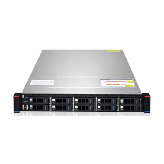
Qtech 1U dual server is divided into 1U4 bay, 1U10 are available in various models. This product features low energy consumption, flexible expansion, high reliability, easy management and easy deployment. -
Page 3: Table Of Contents
3.2. 6. If you use an active cooling fan, please connect the fan power cord to the motherboard socket marked as CPU0_FAN/CPU1_FAN.Memory installation 3.3. Hard disk installation 3.4. Fan module installation 3.5. Installation Steps of Two 2.5-inch Non-Hot Swappable Hard Disks 3.6. Introduction to front panel www.qtech.ru... - Page 4 Make sure the motherboard supports IPMI functionality Enter the BIOS settings IPMI function 7.2. IPMI function quickly explain Enter the operation interface IPMI Management System Content KVM Remote Management Introduction 7.3. Other ways to connect IPMI IPMI driver IPMI tools and other open source software www.qtech.ru...
-
Page 5: General Safety Issues
If you are not sure if you have a safe grounding protection, contact the appropriate agency or electrician for confirmation. If you need to reel cable wiring, please contact QTECH Technology Co., Ltd. to provide advice. Please use a three-core power cord and socket with grounding protection. Improper grounding may result in leakage, explosion, or even personal injury. -
Page 6: Product Toxic And Hazardous Substances Or Elements Name And Content Identification Table
Please keep the environment clean and avoid dust. The working temperature of the equipment is 10°C~35°C and the humidity is 35%~80%. Please promptly back up important data. QTECH Technology Co., Ltd. is not responsible for data loss caused by any situation. - Page 7 Hardware installation manual Qtech Platform 2U Server Product Technical Manual Mechanical components (fans, radiators, motors, etc.) Printed Circuit Components - PCA* Cable/wire/con nector Hard disk drive Harmful Substance Hexavalen cadmiu Polybrominate Part Name lead PBDE d biphenyls chromium (Pb) (Hg)
-
Page 8: Warning Notice
Note: This table shows the status of toxic and hazardous substances contained in all possible parts of QTECH server, memory and workstation products. Customers can refer to this table to check the situation of toxic and hazardous substances contained in the purchased parts. -
Page 9: Other Important Description
Choosing a suitable environment for the computer helps the computer run stably and can extend the life of the computer. QTECH Technology Co., Ltd. reserves the right of final interpretation of the above terms and conditions 1.5. Other important description "If the device is marked with an identifier, it means that the device affixed with this identifier is... -
Page 10: Chapter 2 Product Introduction
Qtech Platform 2U Server Product Technical Manual 2.1. System Introduction The Qtech 1U server is a new generation of 1U dual cabinet server with a wide range of applications that QTECH has developed for Internet, IDC (Internet Data Center), cloud computing, enterprise market and telecom service applications. - Page 11 Hardware installation manual Qtech Platform 2U Server Product Technical Manual chipset Intel® C612 Series Server-Specific Chipset Each DIMM support 32GB(RDIMM)/64GB(LRDIMM) maximumly Maximum 1024GB for whole motherboard DDR4 2133*/ 1866 /1600 /1333RDIMM/LRDIMM/NVDIMM 16pcs DIMM 8 channel ,support1024GB DDR4 maximumly ,2133MHz ECC RDIMM and LRUDIMM 10x SATA 3.0 ports...
-
Page 12: System Structure
Hardware installation manual Qtech Platform 2U Server Product Technical Manual 1x RTL8211E-VB-CG Ethernet PHY Onboard iBMC management module supporting management features management such as IPMI, SOL, KVM Over IP, and virtual media Optional LCD Management Module Virtualization VMWare ESXi 6.0, Nutanix, Hyper-V... -
Page 13: System Model Specifications
Hardware installation manual Qtech Platform 2U Server Product Technical Manual 2.3. System model specifications 1U4 tray 3.5 inch disk model www.qtech.ru... - Page 14 Qtech Platform 2U Server Product Technical Manual Features Technical specifications model size 1U cabinet type, standard with guide rails, maximum depth: 640 mm Supports 1 or 2 Intel Haswell-EP E5-2600 V3 series processor(135W processor maximumly), Brodwell EP processoris compatible chipset Intel®...
- Page 15 Hardware installation manual Qtech Platform 2U Server Product Technical Manual Front Bay: Up to 4 hot-swappable 3.5/2.5-inch SAS/SATA (HDD/SSD) Drive bays Front Bay: Up to 10 hot-swappable 2.5-inch SAS/SATA (HDD/SSD) Rear Bay: Up to 2 hot-swappable 2.5-inch SAS/SATA (HDD/SSD) power supply Platinum-class 550W, 770Whot swappable redundant power supply Front port: 2 USB2.0...
- Page 16 Qtech Platform 2U Server Product Technical Manual 1U10 2.5 inch disk type Features Technical specifications model size 1U cabinet type, standard with guide rails, maximum depth: 640 mm Supports 1 or 2 Intel Haswell-EP E5-2600 V3 series processor(135W processor maximumly), Brodwell EP processoris compatible chipset Intel®...
-
Page 17: System Components Introduction
Hardware installation manual Qtech Platform 2U Server Product Technical Manual Front Bay: Up to 4 hot-swappable 3.5/2.5-inch SAS/SATA (HDD/SSD) Drive bays Front Bay: Up to 10 hot-swappable 2.5-inch SAS/SATA (HDD/SSD) Rear Bay: Up to 2 hot-swappable 2.5-inch SAS/SATA (HDD/SSD) power supply Platinum-class 550W, 770Whot swappable redundant power supply Front port: 2 USB2.0... -
Page 18: Chassis Structure
Hardware installation manual Qtech Platform 2U Server Product Technical Manual Chassis Structure Description Base Rear Windows Ventilation wall Hard disk module Front cover Top cover Handle Hard Drive bracket www.qtech.ru... -
Page 19: Front Panel Lights And Buttons Instructions
Hardware installation manual Qtech Platform 2U Server Product Technical Manual Front panel lights and buttons instructions LED Status Description Picture LED Appearance Description ① LOGO label (labeling or customized acrylic label) The green light is on The device is on ②... -
Page 20: Rear Window Contruction
Hardware installation manual Qtech Platform 2U Server Product Technical Manual ④ The green light The system is running flashes normally ⑤ The yellow light is on Alarm indication, including system alarm, fan alarm, power alarm, etc.; the specific can be viewed... -
Page 21: Motherboard Components
Hardware installation manual Qtech Platform 2U Server Product Technical Manual Motherboard components All the models share the mainboard components. The interface description is as follows Connector name Function description CONN2 VGA and COM overlay connector www.qtech.ru... - Page 22 Hardware installation manual Qtech Platform 2U Server Product Technical Manual JLAN3 Gigabit service network port 1 JLAN2 Gigabit service network port 2 JLAN1 Dual gigabit service network ports CONN1 Dual USB3.0 and IPMI dedicated network port overlay connector JUSB3 Dual USB3.0 overlay connector...
- Page 23 Hardware installation manual Qtech Platform 2U Server Product Technical Manual JUSB4 Vertically insert USB3.0 Connector in the board COM Connector in the board, can be connected to the front JCOM1 panel with an extension cable as needed TPM/80Port Connector, can be...
- Page 24 Hardware installation manual Qtech Platform 2U Server Product Technical Manual SATA5 SATA Connector5,SATA3.0 6Gb/s SATA6 SATA Connector6,SATA3.0 6Gb/s SATA7 SATA Connector7,SATA3.0 6Gb/s SATA8 SATA Connector8,SATA3.0 6Gb/s SATA9 SATA Connector9,SATA3.0 6Gb/s SATA10 SATA Connector10,SATA3.0 6Gb/s SYS_FAN1 System FAN1 SYS_FAN2 System FAN2...
- Page 25 Hardware installation manual Qtech Platform 2U Server Product Technical Manual ATX PWR 24Pin Connector, used connect to the power supply, definition complies with the SSI specification ATX PWR 8Pin Connector, used to connect the power supply, the pin definition complies with...
- Page 26 Hardware installation manual Qtech Platform 2U Server Product Technical Manual CPU0_SLOT2 PCI-E 3.0 X16 PCIE X16 Connector is from CPU0 CPU1_SLOT3 PCI-E 3.0 X8 PCIE X8 Connector is from CPU1 CPU1_SLOT2 PCI-E 3.0 X16 PCIE X16 Connector, the actual (X8 LINK) Link is PCIE3.0 X8 from...
-
Page 27: Hard Disk Backplane Assembly
Hardware installation manual Qtech Platform 2U Server Product Technical Manual the management software developed by Intel for its Chipset. When updating the BIOS with ME FW online, the jumper must be installed and removed after the update is complete. In other cases, the jumper is not required. - Page 28 Hardware installation manual Qtech Platform 2U Server Product Technical Manual Device Numbering Functional description description 1. Maximum support 12G/b SAS hard drive; SAS/SATA hard 2. Maximum support 6G/b SATA hard disk; disk connector 3. Support SAS/SATA hard disk hot swap.
- Page 29 Hardware installation manual Qtech Platform 2U Server Product Technical Manual 2 ATX Power Backplane power transfer connector for input 5, 6 transmission of 12V power 7-12 Sockets of 4 temperature control fans MINI SAS HD(SFF- Used for transmission of 12G/b SAS or 6G/b 8643) 12Gb High SATA signals.
-
Page 30: Install Rear Backplane 2*2.5
Hardware installation manual Qtech Platform 2U Server Product Technical Manual ITEM Description Function Backplane power transfer connector for 1, 2, 3 3 ATX Power input transmission of 12V power.. 4 Sockets of 4PIN 4, 5, temperature control Control FAN RPM and backplane temperature... - Page 31 Hardware installation manual Qtech Platform 2U Server Product Technical Manual Install two 2.5-inch hard disks on HDD tray. Insert two 2.5-inch hard disks into the rear hard disk module. www.qtech.ru...
-
Page 32: Hard Disk Label
Hardware installation manual Qtech Platform 2U Server Product Technical Manual The installation effect is as follows: Note for : if the customer selects two 2.5-inch hot swap hard disks, they must be equipped with CRPS power supply. Hard disk label ... -
Page 33: System Fan
Hardware installation manual Qtech Platform 2U Server Product Technical Manual Hard disk status Green LED Yellow LED Hard disk is not in place Hard disk in place, but no data activity The flash frequency of Hard disk in place, and normal activities... -
Page 34: Chapter 3 Installing System Components
Hardware installation manual Qtech Platform 2U Server Product Technical Manual 3.1. CPU installation Precautions: 1. Please purchase Intel CPU through formal channels. 2. Please make sure that the purchased processor specification belongs to the supported type of this motherboard. 3. If you buy a bulk CPU separately, please make sure that your CPU uses a Gooxi-certified radiator. - Page 35 Hardware installation manual Qtech Platform 2U Server Product Technical Manual 3. Push the left fixed wrench in the direction of the arrow and lift the upper cover of the installation box (G), hold the edge, and gently lift the upper cover of the installation box (H).
- Page 36 Hardware installation manual Qtech Platform 2U Server Product Technical Manual 4. Align the CPU with the socket, make sure that the triangle mark of the CPU is aligned with the triangle mark on the socket, and put the CPU into the socket carefully.
- Page 37 Hardware installation manual Qtech Platform 2U Server Product Technical Manual 6. Push down the right fixing wrench (I), make sure the edge of the upper cover of the installation box is fixed by the wrench (J), and then insert the right fixing wrench into the fixing buckle.
-
Page 38: Installation Of Cpu Radiator
Hardware installation manual Qtech Platform 2U Server Product Technical Manual 7. Push down the left fixed wrench (L), and then insert it into the fixed buckle (M). 3.3 Installation of CPU radiator 1.3.1. 1. Take out the radiator and apply appropriate amount of thermal silicone paste on the bottom of the radiator. -
Page 39: If You Use An Active Cooling Fan, Please Connect The Fan Power Cord To The Motherboard Socket Marked As Cpu0_Fan/Cpu1_Fan.memory Installation
Hardware installation manual Qtech Platform 2U Server Product Technical Manual 5. Reverse the sequence of this process to remove the heat sink. 3.2. 6. If you use an active cooling fan, please connect the fan power cord to the Memory installation motherboard socket marked as CPU0_FAN/CPU1_FAN. - Page 40 Hardware installation manual Qtech Platform 2U Server Product Technical Manual 3. In order to achieve the most ideal compatibility, please use memory modules with the same CAS latency value. It is recommended that you use the same model of memory produced by the same manufacturer.
- Page 41 Hardware installation manual Qtech Platform 2U Server Product Technical Manual Note: Be careful when installing or removing DIMM memory modules to prevent any possible damage to the DIMMs or their respective sockets. Installation: insert the memory module vertically and press the location of the memory slot snap, taking care to align the bottom of the notch.
-
Page 42: Hard Disk Installation
Hardware installation manual Qtech Platform 2U Server Product Technical Manual 3.3. Hard disk installation 1. Installing a 3.5-inch hard disk 1.1. Put the hard disk in the tray 1.2. There are 4 countersunk screws on the left and right sides to lock the hard disk (the screw head must not protrude from the slide surface on both sides of the tray) www.qtech.ru... - Page 43 Hardware installation manual Qtech Platform 2U Server Product Technical Manual Installing a 2.5-inch hard disk 1.1. Put the hard disk in the tray 1.2. The bottom four countersunk screws lock the hard disk (screw head protrudes from the underside of the tray)
- Page 44 Hardware installation manual Qtech Platform 2U Server Product Technical Manual Hard disk tray assembly installed in the chassis 1.1. With the hard disk wrench open, push it into the chassis www.qtech.ru...
- Page 45 Hardware installation manual Qtech Platform 2U Server Product Technical Manual 1.2. When the hard disk gold finger touches the backplane device, turn the wrench in the direction of the arrow. 1.3. Hard Disk Installation in Place www.qtech.ru...
-
Page 46: Fan Module Installation
Hardware installation manual Qtech Platform 2U Server Product Technical Manual 3.4. Fan module installation Install 8 soft nails to the fan as shown in the figure below Steps: Insert the hot swap fan into the fan socket, as shown in the figure below. - Page 47 Hardware installation manual Qtech Platform 2U Server Product Technical Manual Complete the installation, as shown in the following figure: Installation of 4 fans completed, final effect drawing: www.qtech.ru...
-
Page 48: Installation Steps Of Two 2.5-Inch Non-Hot Swappable Hard Disks
Hardware installation manual Qtech Platform 2U Server Product Technical Manual 3.5. Installation Steps of Two 2.5-inch Non-Hot Swappable Hard Disks Remove the screws marked at the following figure, lift the top cover and remove it. As shown in the figure below:... - Page 49 Hardware installation manual Qtech Platform 2U Server Product Technical Manual Fix the two 2.5 inch hard disks with expandable bracket, respectively The final installation effect is as follows www.qtech.ru...
- Page 50 Hardware installation manual Qtech Platform 2U Server Product Technical Manual Install the expandable hard disk to the chassis, as shown in the figure below: The final installation effect of expandable hard disk shown in the figure below www.qtech.ru...
- Page 51 Hardware installation manual Qtech Platform 2U Server Product Technical Manual www.qtech.ru...
-
Page 52: Introduction To Front Panel
Hardware installation manual Qtech Platform 2U Server Product Technical Manual 3.6. Introduction to front panel The mainboard Front Panel has 2 rows of 24 Pin Connectors, with foolproof design (Pin4 foolproof design). This connector is reserved, mainly to connect to the front panel LED, Power Button, etc. - Page 53 Hardware installation manual Qtech Platform 2U Server Product Technical Manual Connect the non- maskable interrupt NMIBTN Ground button, the software does not currently support P5V_AUX The power status indicator in the PWR_LED+ PWR_LED- motherboard, lights up when PWROK Hard disk working status...
- Page 54 Hardware installation manual Qtech Platform 2U Server Product Technical Manual Business network port 3 activity indicator, synchronized with the NIC_LED+ NIC_LED- network port 3 active light, flashes when there is data access. Business network port 4 activity indicator, synchronized with the...
-
Page 55: Chapter 4 System Cabinet Installation
Hardware installation manual Qtech Platform 2U Server Product Technical Manual 4. CHAPTER 4 SYSTEM CABINET INSTALLATION 1. Step 1. After removing the inner rail from the rail, push the middle rail into the rail 1.1. Pull out the inner rail from the guide rail, and you can hear a click and stop 1.2. - Page 56 Hardware installation manual Qtech Platform 2U Server Product Technical Manual Note: When removing the inner rail from the chassis, unlock the buckle in the inner rail as shown in the figure 3. Step 3. Install the guide rail to cabinet (symmetry between the left and right guide rails, please repeat the installation) 3.1.
- Page 57 Hardware installation manual Qtech Platform 2U Server Product Technical Manual Note: To remove the rail from the cabinet, unlock the buckle in the rail as shown 4. Step 4. Install the server to cabinet. 4.1. Pull out the middle rails on both sides of the cabinet and hear a click and stop.
- Page 58 Hardware installation manual Qtech Platform 2U Server Product Technical Manual 4.5. Open the front mounting ears on both sides and use a screwdriver to tighten the screws. Complete step 4. Note: To remove the server from the cabinet, unlock the screws on both sides and the white button, as shown in the figure www.qtech.ru...
-
Page 59: Chapter 5 Bios Parameter Setting Instructions
Hardware installation manual Qtech Platform 2U Server Product Technical Manual 5. CHAPTER 5 BIOS PARAMETER SETTING INSTRUCTIONS 5.1. Enter BIOS Setup interface Steps: 1. Power on the server board and connect the keyboard; 2. During the POST process, observe the prompt at the bottom left of the Logo screen and enter the BIOS Setup screen. - Page 60 Hardware installation manual Qtech Platform 2U Server Product Technical Manual Server Board Information Project Version: Displays the BIOS version of the board. Build Date and Time: Displays the compilation date and time of the board BIOS. Manufacturer: Display the board manufacturer.
- Page 61 Hardware installation manual Qtech Platform 2U Server Product Technical Manual Processor Frequency: CPU frequency information. Processor 1 Version CPU1 specific model information. Processor 2 Version CPU2 specific model information. PCH: PCH model and version information RC Revision: Displays RC code version information.
-
Page 62: Advanced Menu Description
Hardware installation manual Qtech Platform 2U Server Product Technical Manual Advanced menu description Main interface Please be careful when changing the menu option settings of Advanced. Incorrect values may cause system failure. HW Monitor Configuration This project mainly monitors the temperature of the motherboard, the voltage and temperature of the CPU, the speed of the CPU fan, the speed of the system fan, etc. - Page 63 Hardware installation manual Qtech Platform 2U Server Product Technical Manual 1. ACPI settings www.qtech.ru...
- Page 64 Hardware installation manual Qtech Platform 2U Server Product Technical Manual Enable ACPI Auto Configuration [Disabled]: This item has two options [Enabled] [Disabled], you can enable or disable ACPI. Enable Hibernation [Enabled]: 此 项 允 许 您 开 启 或 turn off闭休眠功能...
- Page 65 Hardware installation manual Qtech Platform 2U Server Product Technical Manual Serial Port 2 Configuration: :此项有[Serial PortEnabled] [D isabled] Two options, you can enable and disable serial port debugging. Change Setting: can be selected as manual or automatic mode Serial control management settings ConSole Redirection [Enabled] 此项用户可以开启和关闭控制面板...
- Page 66 Hardware installation manual Qtech Platform 2U Server Product Technical Manual ConSole Redirection Settings This item is the reset direction setting of the console. Terminal Type-[VT100]: ASCII character setting. -[VT100+]: Expand VT100 to support colors, function keys, etc. -[VT-UTF8]: Use UTF8 encoding to map one or more bytes to Unicode characters.
- Page 67 Hardware installation manual Qtech Platform 2U Server Product Technical Manual Stop Bits [1]:The termination number refers to the terminal of the serial data packet. (The starting number refers to the starting end). The standard setting is 1 termination digit, and devices with slow communication speed may require more than 1 termination digit.
- Page 68 Hardware installation manual Qtech Platform 2U Server Product Technical Manual 6. USB settings Legacy USB Support [Enabled] 此项目允许您开启和 turn off U S B 闭 equipment. If it is [Auto], the system will detect whether there is a USB device when it is turned on; if so, the USB controller backward compatibility mode is turned on;...
-
Page 69: 3Intelrcsetup
Hardware installation manual Qtech Platform 2U Server Product Technical Manual USB Mass Storage Driver Support USB storage device driver control switch, the menu options are: Enabled: On Disabled: Off Default: Enabled 1.5.2. 3IntelRCSetup 1. Processor settingsThis item allows you to know more clearly the information of the central processing unit and change the relevant settings of the central processing unit. - Page 70 Hardware installation manual Qtech Platform 2U Server Product Technical Manual Per-Socket Configuration This item can set the number of CPU cores for each CPU interface. Hyper-threading (All):Turn hyperthreading on and off Execute Disable Bit:When disabled, the XD function flag is forced to return to 0 all the time.
- Page 71 Hardware installation manual Qtech Platform 2U Server Product Technical Manual CPU C State Control:Set a series of options to enhance CPU performance. CPU T State Control:Set whether the CPU can be throttled by the system. Throttling will save more energy.
- Page 72 Hardware installation manual Qtech Platform 2U Server Product Technical Manual 4. List of memory topologies:Show memory list www.qtech.ru...
- Page 73 Hardware installation manual Qtech Platform 2U Server Product Technical Manual 5. PCH configuration PCH sSATA Configuration:sSATA configuration SATA Controller:Turn on or turn off the sSATA controller SATA Mode options:SATA Led Locate function on and off SATA Port 0-3 setting options:Including port opening and closing, hot plug opening and closing, and SATA type selection.
- Page 74 Hardware installation manual Qtech Platform 2U Server Product Technical Manual PCH SATA Configuration:SATA configuration SATA Controller:Turn on or turn off the sSATA controller SATA Mode options:SATA Led Locate function on and off SATA Port 0-5 setting options:Including port opening and closing, hot plug opening and closing, and SATA type selection.
- Page 75 Hardware installation manual Qtech Platform 2U Server Product Technical Manual USB Controller Configuration:USB controller configuration xHCI Mode:The operating mode of the xHCI controller can be selected as Smart Auto/Enabled/Disabled/Manual Auto/ www.qtech.ru...
- Page 76 Hardware installation manual Qtech Platform 2U Server Product Technical Manual 6.General ME Configuration:ME configuration information www.qtech.ru...
- Page 77 Hardware installation manual Qtech Platform 2U Server Product Technical Manual PCI Express Device Configuration:PCI-E device configuration Onboard Lan 1&2:Network port 1&2 settings Onboard Lan 3 (Down):Network port 3 settings Onboard Lan 4 (Up):Network port 4 settings CPU0 PCIE X16 Slot 1:The opening and closing of the port, the connection speed setting...
- Page 78 Hardware installation manual Qtech Platform 2U Server Product Technical Manual Restore AC Power Loss [Last State]:Set the state after the power is reloaded as on/off/last state Displays information such as the version, status, and function of the server ME. www.qtech.ru...
-
Page 79: Server Remote Management Menu (Server Mgmt)
Hardware installation manual Qtech Platform 2U Server Product Technical Manual 2.5.2. Server Remote Management Menu (Server MGMT) BMC self test log:BMC self-check record www.qtech.ru... - Page 80 Hardware installation manual Qtech Platform 2U Server Product Technical Manual Erase Log【No】:Delete log options, respectively [Yes, On every reset] [No] When log is full【Clear Log】:The operation after the log file is full is [Clear Log] [Do not log any more] BMC network configuration:BMC network settings www.qtech.ru...
-
Page 81: Security Menu (Security)
Hardware installation manual Qtech Platform 2U Server Product Technical Manual Configuration Address source [Unspecified]: Configuration URL method, respectively [Unspecified] [Static] [DynamicBmcDhcp] [DynamicBmcNonDhcp] BMC Warm Reset:BMC restart 3.5.2. Security menu (Security) This menu allows you to create a new password or change an existing password, turn on or off the secure boot state, and let users set the system mode state by themselves. - Page 82 Hardware installation manual Qtech Platform 2U Server Product Technical Manual Administrator Password: Administrator password If you have set an administrator password, it is recommended that you enter the administrator password to enter the system, otherwise, you can only see or change part of the BIOS.
- Page 83 Hardware installation manual Qtech Platform 2U Server Product Technical Manual 2. When the "Enter Current Password" window appears, enter the current password and press the "Enter" key. 3. When the "Create New Password" window appears, enter the password you want to set and press the "Enter"...
-
Page 84: Boot Menu (Boot)
Hardware installation manual Qtech Platform 2U Server Product Technical Manual 3. When the "Create New Password" window appears, enter the password you want to set and press the "Enter" key. 4. Enter the password again in the pop-up confirmation window to confirm that the password is entered correctly. -
Page 85: Exit Bios Menu (Save & Exit)
Hardware installation manual Qtech Platform 2U Server Product Technical Manual This item is used to display the Gooxi brand Logo, and the default setting is [Enabled]. Optional settings are: [Enabled] and [Disabled]. Boot Option Priorities:Boot priority options Network Device BBS Priorities:Set the boot priority of the smart... -
Page 86: Chapter 6 Raid Setup Instructions
Hardware installation manual Qtech Platform 2U Server Product Technical Manual Save Changes and Reset:Save the changes you have made, exit the BIOS setup program and restart. Discard Changes and Reset:This item can discard the changes you have made, exit the BIOS setup program and restart. - Page 87 Hardware installation manual Qtech Platform 2U Server Product Technical Manual nor fault tolerance. If a disk (physical) is damaged, all data will be lost, and the degree of danger is equivalent to that of JBOD. 2.RAID1 The main function of RAID1 is "Data Mirroring", that is, data mirroring. The principle is that while storing data on the main hard disk, the same data is also written on the mirrored hard disk.
- Page 88 Hardware installation manual Qtech Platform 2U Server Product Technical Manual drives. RAID 5 does not back up the stored data, but stores the data and the corresponding parity information on each of the disks that make up the RAID5, and the parity information and the corresponding data are separately Stored on different disks.
-
Page 89: Install Hard Disk
Hardware installation manual Qtech Platform 2U Server Product Technical Manual 2.6.1. 6.1.2 Install Hard Disk This motherboard supports SATA hard drives. For the best performance, when you want to establish an array mode setting, please use hard drives with the same model and capacity as much as possible. - Page 90 Hardware installation manual Qtech Platform 2U Server Product Technical Manual 2. Enter the Software Feature Mask Configuration item, you can see that the motherboard RAID0, RAID1, RAID5, RAID10 are all set to [Enabled], and Intel Rapid Recovery Technology is also set to [Enabled].
-
Page 91: Intel® Rapid Storage Technology Enterprise Sata Option Rom Utility Setup Program
Hardware installation manual Qtech Platform 2U Server Product Technical Manual Intel® Rapid Storage Technology Enterprise SATA Option ROM 4.6.1. Utility setup program Intel® The Rapid Storage Technology Enterprise SATA Option ROM utility program can create RAID0, RAID1, RAID5, RAID10 through the SATA hard disk connected to the South Bridge chip built-in on the motherboard. - Page 92 Hardware installation manual Qtech Platform 2U Server Product Technical Manual Table 1-2 RSTe configuration interface description Options Instructions MAIN MENU Located on the upper side of the interface, you can perform the following operations: (main menu) Create RAID Volume: Configures a RAID volume.
- Page 93 Hardware installation manual Qtech Platform 2U Server Product Technical Manual 2. As shown in Figure 1-16, select Create RAID Volume from the RSTe configuration page and press Enter. Figure 1-16 RSTe configuration interface 3. Go to the page shown in Figure 1-17. Set parameters in the Name, RAID Level, Disks, Strip Size, and Capacity columns.
- Page 94 Hardware installation manual Qtech Platform 2U Server Product Technical Manual parameter Instructions Name The name of the RAID. RAID Level RAID level. RAID levels determine logical disk performance, fault tolerance, and capacity. Disks Select the member disk that makes up RAID. Select the Disks tab and press Enter.
- Page 95 Hardware installation manual Qtech Platform 2U Server Product Technical Manual Figure 1-19 RSTe configuration interface 3. Enter the interface as shown in Figure 1-20. Select the disk to be configured as a hot spare disk and press SPACE. Then press Enter. In the prompt box, enter y and press Enter to complete the configuration of the hot spare disk.
- Page 96 Hardware installation manual Qtech Platform 2U Server Product Technical Manual Delete RAID: 1. Enter RSTe configuration interface. 2. As shown in Figure 1-22, select Delete RAID Volume from the RSTe configuration page and press Enter. Figure 1-22 RSTe configuration interface 3.
-
Page 97: Lsi Sas3008 Group Raid
Hardware installation manual Qtech Platform 2U Server Product Technical Manual 6.2. LSI SAS3008 Group RAID Configuring RAID in UEFI Boot Mode Enter the RAID card configuration interface 1. During the server startup, press Delete/Esc as prompted to enter the BIOS Setup interface. - Page 98 Hardware installation manual Qtech Platform 2U Server Product Technical Manual 4. Enter the RAID card configuration interface, as shown in the following figure www.qtech.ru...
- Page 99 Hardware installation manual Qtech Platform 2U Server Product Technical Manual Common tasks Create RAID: 1. Select Create Configuration to enter the Configure RAID interface, as shown in the following figure www.qtech.ru...
- Page 100 Hardware installation manual Qtech Platform 2U Server Product Technical Manual 2. Enter the screen shown below, select Select RAID Level, set the RAID level, and press Enter. www.qtech.ru...
- Page 101 Hardware installation manual Qtech Platform 2U Server Product Technical Manual 3. Select Selcect Physical Disks to enter the RAID page of the selected group RAID www.qtech.ru...
- Page 102 Hardware installation manual Qtech Platform 2U Server Product Technical Manual 4. Select the disk you want to use to configure the RAID, [Enabled] is selected, select Apply Changes, and press Enter. www.qtech.ru...
- Page 103 Hardware installation manual Qtech Platform 2U Server Product Technical Manual 5. Change Confirm to Enabled and select Yes to complete RAID configuration www.qtech.ru...
- Page 104 Hardware installation manual Qtech Platform 2U Server Product Technical Manual Configure the hot spare disk: Hot spares are used only for redundant RAID levels. The capacity of the hot spare disk is larger than the capacity of a RAID single member disk used to contribute to the RAID.
- Page 105 Hardware installation manual Qtech Platform 2U Server Product Technical Manual 2. Select the hot spare disk, set the hot spare disk to Enabled, select Assign Global Hotspare Disk, and press enter to complete the hot spare disk configuration. www.qtech.ru...
- Page 106 Hardware installation manual Qtech Platform 2U Server Product Technical Manual Delete RAID: 3. Select Virtual Disk Management and press enter. www.qtech.ru...
- Page 107 Hardware installation manual Qtech Platform 2U Server Product Technical Manual 4. Select Select Virtual Disk Operations and press enter. www.qtech.ru...
- Page 108 Hardware installation manual Qtech Platform 2U Server Product Technical Manual 5. Select Delete Virtual Disk and press enter. www.qtech.ru...
- Page 109 Hardware installation manual Qtech Platform 2U Server Product Technical Manual 6. Change Confirm to Enabled, check Yes, and press enter to finish deleting RAID. www.qtech.ru...
-
Page 110: Legacy Boot Mode To Configure Raid
Hardware installation manual Qtech Platform 2U Server Product Technical Manual Legacy boot mode to configure RAID 1. During the BIOS startup process, as shown in Figure 2-1, press Ctrl+C. Figure 2-1 Entering the prompt www.qtech.ru... - Page 111 Hardware installation manual Qtech Platform 2U Server Product Technical Manual 2. Enter the interface shown in Figure 2-2. Please refer to the key operation hints at the bottom border of the interface to navigate and modify the settings in the interface.
- Page 112 Hardware installation manual Qtech Platform 2U Server Product Technical Manual 4. Select to enter the RAID Properties menu, press enter, enter the group raid interface, as shown below, can be in the current interface group raid1, raid0, raid1E/10 and other operations: www.qtech.ru...
-
Page 113: Lsi 9361-8I Group Raid
Hardware installation manual Qtech Platform 2U Server Product Technical Manual 6.3. LSI 9361-8i Group RAID Configuring RAID in UEFI Boot Mode Enter the RAID card configuration interface 1. During the server startup, press Delete/Esc as prompted to enter the BIOS Setup interface. - Page 114 Hardware installation manual Qtech Platform 2U Server Product Technical Manual Controller Select Controller Management to view and manage controller properties Management and perform tasks such as clear controller events, schedule and run controller events, and run patrol reads. Virtual Drive...
- Page 115 Hardware installation manual Qtech Platform 2U Server Product Technical Manual 2. Enter the interface as shown in Figure 3-3. Select the disk to be configured and press Enter. Figure 3-3 Drive Management interface www.qtech.ru...
- Page 116 Hardware installation manual Qtech Platform 2U Server Product Technical Manual 3. Enter the interface as shown in Figure 3-4. Select Operation and press Enter. In the dialog box that is displayed, select Make Unconfigured Bad and press Enter. Figure 3-4 Operation interface...
- Page 117 Hardware installation manual Qtech Platform 2U Server Product Technical Manual 4. Go to the screen shown in Figure 3-5. Select Go and press Enter. Figure 3-5 Select Go www.qtech.ru...
- Page 118 Hardware installation manual Qtech Platform 2U Server Product Technical Manual 5. Enter the interface shown in Figure 3-6 to complete the switch disk mode operation. Figure 3-6 Complete Switch Disk Mode www.qtech.ru...
- Page 119 Hardware installation manual Qtech Platform 2U Server Product Technical Manual Create RAID: 1. As shown in Figure 3-7, select Configuration Management on the RAID card configuration page and press Enter. Figure 3-7 RAID card configuration interface www.qtech.ru...
- Page 120 Hardware installation manual Qtech Platform 2U Server Product Technical Manual 2. Enter the interface as shown in Figure 3-8. Select Create Virtual Drive and press Enter. Figure 3-8 Select Create Virtual Drive www.qtech.ru...
- Page 121 Hardware installation manual Qtech Platform 2U Server Product Technical Manual 3. Enter the interface as shown in Figure 3-9. Select Select RAID Level, set the RAID level, and press Enter. Figure 3-9 Setting the RAID Level www.qtech.ru...
- Page 122 Hardware installation manual Qtech Platform 2U Server Product Technical Manual Enter the interface as shown in Figure 3-10. Select Select Drives From, set the RAID disk capacity source, and press Enter. [Unconfigured Capacity] Indicates that the capacity is from the remaining capacity of the configured RAID disk.
- Page 123 Hardware installation manual Qtech Platform 2U Server Product Technical Manual 5. Enter the interface as shown in Figure 3-11. Select Select Drives and press Enter. Figure 3-11 Select Select Drives www.qtech.ru...
- Page 124 Hardware installation manual Qtech Platform 2U Server Product Technical Manual 6. Enter the interface as shown in Figure 3-12. Select the disk to use for RAID configuration. [Enabled] is selected, select Apply Changes, and press Enter. If the status of the disk is JBOD or Unconfigured Bad, it cannot be selected.
- Page 125 Hardware installation manual Qtech Platform 2U Server Product Technical Manual 7. Enter the interface as shown in Figure 3-13 and perform the corresponding settings (see Table 1-3 for parameter descriptions). Then select Save Configuration and press Enter. Figure 3-13 Setting RAID parameters...
- Page 126 Hardware installation manual Qtech Platform 2U Server Product Technical Manual Parameter Description parameter Instructions Virtual Drive Name The name of the RAID, which only supports letters, numbers, and underscores. It is case insensitive Virtual Drive Size RAID capacity size Virtual Drive Size...
- Page 127 Hardware installation manual Qtech Platform 2U Server Product Technical Manual Write Policy Write caching strategy is divided into Write Through, Write Back, and Write Back. I/O Policy I/O policy, divided into Cached (cache mode) and Direct (direct read- write mode)
- Page 128 Hardware installation manual Qtech Platform 2U Server Product Technical Manual 9. Enter the screen shown in Figure 2-19 to complete the RAID configuration. Select OK to return to the RAID card configuration interface. Figure 2-19 Complete RAID configuration www.qtech.ru...
- Page 129 Hardware installation manual Qtech Platform 2U Server Product Technical Manual 10. As shown in Figure 3-15, select Virtual Drive Management from the RAID card configuration page and press Enter. Figure 3-15 RAID card configuration interface www.qtech.ru...
- Page 130 Hardware installation manual Qtech Platform 2U Server Product Technical Manual 11. Enter the interface as shown in Figure 3-16. You can see the created RAID, select the RAID to be viewed, and press Enter. Figure 3-16 Vitrual Drive Management interface...
- Page 131 Hardware installation manual Qtech Platform 2U Server Product Technical Manual 12. Enter the interface as shown in Figure 3-17. Select View Associated Drives and press Enter to view the details of the RAID (including the RAID name, level, disk information, etc.).
- Page 132 Hardware installation manual Qtech Platform 2U Server Product Technical Manual Configure the hot spare disk: After RAID is configured, hot spare disks are generally configured to improve data security. You can configure a global hot spare disk or a dedicated hot spare disk as required.
- Page 133 Hardware installation manual Qtech Platform 2U Server Product Technical Manual 2. On the page shown in Figure 3-19, select the disk to be configured as a global hot spare disk and press Enter. Figure 3-19 Drive Management interface www.qtech.ru...
- Page 134 Hardware installation manual Qtech Platform 2U Server Product Technical Manual 3. Go to the screen shown in Figure 3-20. Select Operation, press Enter, select Assign Dedicated Hot Spare Drive, and press Enter. Figure 3-20 Operation interface www.qtech.ru...
- Page 135 Hardware installation manual Qtech Platform 2U Server Product Technical Manual 4. Go to the screen shown in Figure 3-21. Choose Go and press Enter. Figure 3-21 Select Go www.qtech.ru...
- Page 136 Hardware installation manual Qtech Platform 2U Server Product Technical Manual 5. Enter the interface as shown in Figure 3-22. Select Confirm to enable it, select Yes, and press Enter. Figure 3-22 Confirm configuration www.qtech.ru...
- Page 137 Hardware installation manual Qtech Platform 2U Server Product Technical Manual 6. Go to the page shown in Figure 3-23 to complete the configuration of the global hot spare disk. Figure 3-23 Complete configuration of the global hot spare disk www.qtech.ru...
- Page 138 Hardware installation manual Qtech Platform 2U Server Product Technical Manual Delete RAID: 1. As shown in Figure 3-24, select Virtual Drive Management from the RAID card configuration page and press Enter. Figure 3-24 RAID card configuration interface www.qtech.ru...
- Page 139 Hardware installation manual Qtech Platform 2U Server Product Technical Manual 2. Enter the interface as shown in Figure 3-25. Select the logical disk to be deleted and press Enter. Figure 3-25 Logical Disk Management Interface www.qtech.ru...
- Page 140 Hardware installation manual Qtech Platform 2U Server Product Technical Manual 3. Enter the interface as shown in Figure 2-37. Select Operation and press Enter. In the dialog box that is displayed, select Delete Virtual Drive and press Enter. Figure 2-37 Operation interface...
- Page 141 Hardware installation manual Qtech Platform 2U Server Product Technical Manual 4. Go to the screen shown in Figure 2-38. Choose Go and press Enter. Figure 2-38 Select Go www.qtech.ru...
- Page 142 Hardware installation manual Qtech Platform 2U Server Product Technical Manual 5. Enter the interface as shown in Figure 2-39. Choose Confirm, Enabled, Yes, and press Enter. Figure 2-39 Confirm Delete www.qtech.ru...
- Page 143 Hardware installation manual Qtech Platform 2U Server Product Technical Manual 6. Enter the interface as shown in Figure 2-40 to delete the RAID operation. Figure 2-40 Complete RAID Deletion www.qtech.ru...
- Page 144 Hardware installation manual Qtech Platform 2U Server Product Technical Manual Locate the disk location: 1. Locating physical disks 1.1. As shown in Figure 2-41, select Drive Management from the RAID card configuration page and press Enter. Figure 2-41 Select Drive Management...
- Page 145 Hardware installation manual Qtech Platform 2U Server Product Technical Manual 1.2. Enter the Figure 2-42 interface. Select the disk to be located and press Enter. Figure 2-42 Selecting a disk to be located www.qtech.ru...
- Page 146 Hardware installation manual Qtech Platform 2U Server Product Technical Manual 1.3. Go to the Figure 2-43 interface. Choose Operation and press Enter. In the dialog box that is displayed, select Start Locate and press Enter. Figure 2-43 Operation interface www.qtech.ru...
- Page 147 Hardware installation manual Qtech Platform 2U Server Product Technical Manual 1.4. Go to the Figure 2-44 screen. Choose Go and press Enter. Figure 2-44 Select Go www.qtech.ru...
- Page 148 Hardware installation manual Qtech Platform 2U Server Product Technical Manual 1.5. Go to the Figure 2-45 interface to complete the location of the physical disk. Figure 2-45 Positioning the physical disk is complete www.qtech.ru...
- Page 149 Hardware installation manual Qtech Platform 2U Server Product Technical Manual 2. Locating all disks in a logical disk 2.1. As shown in Figure 2-41, select Virtual Drive Management from the RAID card configuration page and press Enter. Figure 2-41 RAID card configuration interface...
- Page 150 Hardware installation manual Qtech Platform 2U Server Product Technical Manual 2.2. Go to the Figure 2-47 screen. Select the logical disk to be located and press Enter. Figure 2-47 Selecting a logical disk to be located www.qtech.ru...
- Page 151 Hardware installation manual Qtech Platform 2U Server Product Technical Manual 2.3. Enter the Figure 2-48 interface. Select Operation and press Enter. In the dialog box that is displayed, select Start Locate and press Enter. Figure 2-48 Operation interface www.qtech.ru...
- Page 152 Hardware installation manual Qtech Platform 2U Server Product Technical Manual 2.4. Go to the screen shown in Figure 2-49. Choose Go and press Enter. Figure 2-49 Select Go www.qtech.ru...
- Page 153 Hardware installation manual Qtech Platform 2U Server Product Technical Manual 2.5. Enter the Figure 2-50 interface to complete the operations for locating all the disk locations in the logical disk. Figure 2-50 Complete positioning of all disks in a logical disk...
- Page 154 Hardware installation manual Qtech Platform 2U Server Product Technical Manual Initialize the logical disk: This function is used to initialize the logical disk internal data space so that it can be used by the operating system. 1. As shown in Figure 2-51, select Virtual Drive Management from the RAID card configuration page and press Enter.
- Page 155 Hardware installation manual Qtech Platform 2U Server Product Technical Manual 2. Enter the interface as shown in Figure 2-52. Select the logical disk to be initialized and press Enter. Figure 2-52 Logical Disk Management Interface www.qtech.ru...
- Page 156 Hardware installation manual Qtech Platform 2U Server Product Technical Manual 3. Go to the screen shown in Figure 2-53. Select Operation and press Enter. In the dialog box that is displayed, select Fast/Slow Initialization and press Enter. Figure 2-53 Operation interface...
- Page 157 Hardware installation manual Qtech Platform 2U Server Product Technical Manual The difference between Fast Initialization and Slow Initialization is that the former can write data immediately, and the latter can wait for the disk space to be completely initialized before writing data.
- Page 158 Hardware installation manual Qtech Platform 2U Server Product Technical Manual 5. Enter the interface shown in Figure 2-55. Select Confirm, Enabled, Yes, and press Enter. Figure 2-55 Confirm initialization www.qtech.ru...
- Page 159 Hardware installation manual Qtech Platform 2U Server Product Technical Manual 6. Enter the interface shown in Figure 2-56 to complete the initialization of logical disk operations. Figure 2-56 complete initialization of the logical disk www.qtech.ru...
- Page 160 Hardware installation manual Qtech Platform 2U Server Product Technical Manual Initialize the physical disk: 1. As shown in Figure 2-57, select Drive Management from the RAID card configuration page and press Enter. Figure 2-57 RAID card configuration interface www.qtech.ru...
- Page 161 Hardware installation manual Qtech Platform 2U Server Product Technical Manual 2. Enter the screen shown in Figure 2-58. Select the disk to be initialized and press Enter. Figure 2-58 Disk Management Interface www.qtech.ru...
- Page 162 Hardware installation manual Qtech Platform 2U Server Product Technical Manual 3. Go to the Figure 2-59 interface. Select Operation and press Enter. In the dialog box that is displayed, select Initialize Drive and press Enter. Figure 2-59 Operation management interface...
- Page 163 Hardware installation manual Qtech Platform 2U Server Product Technical Manual 4. Go to the Figure 2-60 screen. Choose Go and press Enter. Figure 2-60 Select Go www.qtech.ru...
- Page 164 Hardware installation manual Qtech Platform 2U Server Product Technical Manual 5. Enter the interface shown in Figure 2-61. Select Confirm to enable it, select Yes, and press Enter. Figure 2-61 Confirm initialization www.qtech.ru...
- Page 165 Hardware installation manual Qtech Platform 2U Server Product Technical Manual 6. Enter the Figure 2-62 interface to complete the initialization of the physical disk operation. Figure 2-62 Complete initializing the physical disk www.qtech.ru...
- Page 166 Hardware installation manual Qtech Platform 2U Server Product Technical Manual Erase disk data: This function is used to delete internal data of the disk, including erasing physical disk data and logical disk data. 1. Erase physical disk data 1.1. As shown in Figure 2-63, select Drive Management on the RAID card configuration page and press Enter.
- Page 167 Hardware installation manual Qtech Platform 2U Server Product Technical Manual 1.2. Enter the screen shown in Figure 2-64, select the disk to be erased, and press Enter. Figure 2-64 Disk Management Interface www.qtech.ru...
- Page 168 Hardware installation manual Qtech Platform 2U Server Product Technical Manual 1.3. Enter the interface as shown in Figure 2-65. Select Operation and press Enter. In the dialog box that is displayed, select Drive Erase and press Enter. Figure 2-65 Operation interface...
- Page 169 Hardware installation manual Qtech Platform 2U Server Product Technical Manual 1.4. Go to the screen shown in Figure 2-66, press Enter, and then select the erase mode in the dialog box that is displayed (the default mode is recommended: Simple).
- Page 170 Hardware installation manual Qtech Platform 2U Server Product Technical Manual 1.5. Go to the screen shown in Figure 2-67. Choose Go and press Enter. Figure 2-67 Select Go www.qtech.ru...
- Page 171 Hardware installation manual Qtech Platform 2U Server Product Technical Manual 1.6. Enter the interface as shown in Figure 2-68. Select Confirm to enable it, select Yes, and press Enter. Figure 2-68 Confirm Erase www.qtech.ru...
- Page 172 Hardware installation manual Qtech Platform 2U Server Product Technical Manual 1.7. Enter the interface as shown in Figure 2-69 to finish erasing physical disk data. Figure 2-69 Finishing Erasing Physical Disk Data www.qtech.ru...
- Page 173 Hardware installation manual Qtech Platform 2U Server Product Technical Manual To avoid disk failure, do not perform other operations while erasing physical disk data. 2. Erase logical disk data 2.1. As shown in Figure 2-70, select Virtual Drive Management from the RAID card configuration page and press Enter.
- Page 174 Hardware installation manual Qtech Platform 2U Server Product Technical Manual 2.2. Enter the interface as shown in Figure 2-71. Select the logical disk to be erased and press Enter. Figure 2-71 Logical Disk Management Interface www.qtech.ru...
- Page 175 Hardware installation manual Qtech Platform 2U Server Product Technical Manual 2.3. Enter the page shown in Figure 2-72. Select Operation and press Enter. In the dialog box that is displayed, select Virtual Drive Erase and press Enter. Figure 2-72 Operation interface...
- Page 176 Hardware installation manual Qtech Platform 2U Server Product Technical Manual 2.4. Enter the interface shown in Figure 2-73, press Enter, and then select the erase mode in the dialog box that is displayed (The default mode: Simple is recommended). Figure 2-73 Erase Mode screen...
- Page 177 Hardware installation manual Qtech Platform 2U Server Product Technical Manual 2.5. Go to the interface shown in Figure 2-74. Choose Go and press Enter. Figure 2-74 Select Go www.qtech.ru...
- Page 178 Hardware installation manual Qtech Platform 2U Server Product Technical Manual 2.6. Enter the interface as shown in Figure 2-75. Select Confirm to enable it, select Yes, and press Enter. Figure 2-75 Confirm Erase www.qtech.ru...
- Page 179 Hardware installation manual Qtech Platform 2U Server Product Technical Manual 2.7. Enter the interface as shown in Figure 2-76 to erase logical disk data. Figure 2-76 Complete erase logical disk data www.qtech.ru...
- Page 180 Hardware installation manual Qtech Platform 2U Server Product Technical Manual Migrate RAID levels: This function is used to modify the RAID level to meet the configuration requirements without affecting the integrity of the current data. 1. As shown in Figure 2-77, select Virtual Drive Management from the RAID card configuration page and press Enter.
- Page 181 Hardware installation manual Qtech Platform 2U Server Product Technical Manual 2. Enter the interface as shown in Figure 2-78. Select the logical disk to be rebuilt and press Enter. Figure 2-78 Virtual Drive Management interface www.qtech.ru...
- Page 182 Hardware installation manual Qtech Platform 2U Server Product Technical Manual 3. Enter the screen shown in Figure 2-79. Select Operation and press Enter. In the dialog box that is displayed, select Reconfigure Virtual Drive and press Enter. Figure 2-79 Operation interface...
- Page 183 Hardware installation manual Qtech Platform 2U Server Product Technical Manual 4. Go to the screen shown in Figure 2-80. Choose Go and press Enter. Figure 2-80 Select Go www.qtech.ru...
- Page 184 Hardware installation manual Qtech Platform 2U Server Product Technical Manual 5. Enter the screen shown in Figure 2-81. Set the RAID level, select Add Drives, and press Enter. Figure 2-81 Advanced interface www.qtech.ru...
- Page 185 Hardware installation manual Qtech Platform 2U Server Product Technical Manual 6. Enter the screen shown in Figure 2-82. Select the disk to be added, enable it, select Apply Changes, and press Enter. Figure 2-82 Add Drives interface www.qtech.ru...
- Page 186 Hardware installation manual Qtech Platform 2U Server Product Technical Manual 7. Enter the interface as shown in Figure 2-83. Select Confirm to enable it, select Yes, and press Enter. Figure 2-83 Confirming Migration www.qtech.ru...
- Page 187 Hardware installation manual Qtech Platform 2U Server Product Technical Manual 8. Go to the screen shown in Figure 2-84. Select Start Operation and press Enter. Figure 2-84 Start Operation screen www.qtech.ru...
- Page 188 Hardware installation manual Qtech Platform 2U Server Product Technical Manual 9. Go to the screen shown in Figure 2-85. Choose OK and press Enter. Figure 2-85 Select OK www.qtech.ru...
- Page 189 Hardware installation manual Qtech Platform 2U Server Product Technical Manual 10. Enter the interface as shown in Figure 2-86 to check the current migration progress. Figure 2-86 RAID information interface www.qtech.ru...
- Page 190 Hardware installation manual Qtech Platform 2U Server Product Technical Manual Clear disk RAID information: This function is used to clear the RAID residue information in the disk so that the disk can be reused to configure RAID. This feature is commonly used for disks with the mode Unconfigured Bad.
- Page 191 Hardware installation manual Qtech Platform 2U Server Product Technical Manual 3. Go to the screen shown in Figure 2-88. Select Manage Foreign Configuration and press Enter. Figure 2-88 Select Manage Foreign Configuration www.qtech.ru...
- Page 192 Hardware installation manual Qtech Platform 2U Server Product Technical Manual 4. Enter the interface shown in Figure 2-89. Select Clear Foreign Configuration and press Enter. Figure 2-89 Select Clear Foreign Configuration www.qtech.ru...
- Page 193 Hardware installation manual Qtech Platform 2U Server Product Technical Manual 5. Enter the screen shown in Figure 2-90. Select Confirm, Enabled, Yes, and press Enter. Figure 2-90 Confirm Clear www.qtech.ru...
- Page 194 Hardware installation manual Qtech Platform 2U Server Product Technical Manual 6. Enter the screen shown in Figure 2-91 to complete the disk RAID disk clearing operation. Figure 2-91 Clear Disk RAID Completed www.qtech.ru...
-
Page 195: Legacy Boot Mode To Configure Raid
Hardware installation manual Qtech Platform 2U Server Product Technical Manual Legacy boot mode to configure RAID Enter the RAID card configuration interface 1. During the BIOS startup process, as shown in Figure 2-92, press Ctrl+R. Figure 2-92 Press Ctrl+R as prompted during BIOS startup... - Page 196 Hardware installation manual Qtech Platform 2U Server Product Technical Manual 2. Enter the interface shown in Figure 2-93. Please refer to the key operation tips at the bottom border of the interface to navigate and modify the settings in the interface.
- Page 197 Hardware installation manual Qtech Platform 2U Server Product Technical Manual Figure 2-94 Select Create Virtual Drive 2. Go to the screen shown in Figure 2-95. Set the RAID level and press Enter. Figure 2-95 Setting RAID Level 3. Enter the screen shown in Figure 2-96. Select the disk to configure RAID and press Enter.
- Page 198 Hardware installation manual Qtech Platform 2U Server Product Technical Manual 4. Enter the screen shown in Figure 2-97. Set the Size and Name accordingly. Then choose Advanced and press Enter. Figure 2-97 Setting the RAID Name and Capacity 5. Enter the page shown in Figure 2-98. Set related parameters. For details, see Table 1-3. Then select OK and press Enter.
- Page 199 Hardware installation manual Qtech Platform 2U Server Product Technical Manual 6. Enter the interface as shown in Figure 2-99. Choose OK and press Enter to complete the RAID configuration. Figure 2-99 Confirm Create 7. Select the RAID to be viewed and press Enter to view the detailed information of the RAID (including the RAID name, level, disk information, etc.), as shown in Figure 2-100.
- Page 200 Hardware installation manual Qtech Platform 2U Server Product Technical Manual Configure the hot spare disk: After RAID is configured, hot spare disks are generally configured to improve data security. You can configure a global hot spare disk and a dedicated hot spare disk as required.
- Page 201 Hardware installation manual Qtech Platform 2U Server Product Technical Manual 1.2. Go to the screen shown in Figure 2-102, select Make Global HS, and press Enter to complete the configuration of the global hot spare disk. Figure 2-102 Selecting Make Global HS 1.3.
- Page 202 Hardware installation manual Qtech Platform 2U Server Product Technical Manual Delete RAID: This function is used to delete RAID that is damaged or hard to meet the requirements. 1. As shown in Figure 2-104, select the logical disk to be deleted on the VD Mgmt screen and press F2.
- Page 203 Hardware installation manual Qtech Platform 2U Server Product Technical Manual Figure 2-105 Select Delete VD 3. Enter the screen shown in Figure 2-106. Select YES and press Enter to complete the RAID operation. Figure 2-106 Confirming the deletion www.qtech.ru...
- Page 204 Hardware installation manual Qtech Platform 2U Server Product Technical Manual Locate the disk location: This function allows you to quickly find the disk by turning on the blue LED in the corresponding slot of the disk. You can locate a single physical disk or all member disks included in a logical disk.
- Page 205 Hardware installation manual Qtech Platform 2U Server Product Technical Manual Locate->Start: Start disk positioning operation. Locate->Stop: Stops locating disk operations. Initialize the logical disk: This function is used to initialize the internal data space of the disk so that it can be used by the operating system.
- Page 206 Hardware installation manual Qtech Platform 2U Server Product Technical Manual 2. Go to the interface shown in Figure 2-110 and select Initialization->Start FGI. Figure 2-110 Select Initialization->Start FGI BGI: Backgroud Initialization, background initialization, initializing some of the RAID space for writing data, and the rest of the space is initialized in the background.
- Page 207 Hardware installation manual Qtech Platform 2U Server Product Technical Manual FGI: Full Groud Initialization, full initialization, all RAID space initialization, data can be written after the initialization is complete. 3. Enter the interface shown in Figure 2-111. Select YES and press Enter to complete the initialization of the disk operation.
- Page 208 Hardware installation manual Qtech Platform 2U Server Product Technical Manual 1.2. Enter the interface as shown in Figure 2-113. Select the erase mode (use the default mode: Simple) and press Enter. Figure 2-113 Select the erase mode 1.3. Enter the interface shown in Figure 2-114. Select Yes and press Enter to complete the data disk erase operation.
- Page 209 Hardware installation manual Qtech Platform 2U Server Product Technical Manual To avoid disk failure, do not perform other operations while erasing physical disk data. 2. Erase logical disk data 2.1. As shown in Figure 2-115, select the logical disk to be erased on the VD Mgmt screen, and press F2.
- Page 210 Hardware installation manual Qtech Platform 2U Server Product Technical Manual 2.2. Enter the interface as shown in Figure 2-116. Select the erase mode (use the default mode: Simple) and press Enter. Figure 2-116 Selecting the erase mode 2.3. Enter the interface as shown in Figure 2-117. Select Yes and press Enter to complete the logical disk data erase operation.
- Page 211 Hardware installation manual Qtech Platform 2U Server Product Technical Manual Figure 2-117 Confirm Erase Clear disk RAID information: This function is used to clear the RAID residue information in the disk so that the disk can be reused to configure RAID. This feature is commonly used for disks that have the Unconfigured Bad mode.
- Page 212 Hardware installation manual Qtech Platform 2U Server Product Technical Manual 3. In the dialog box that is displayed in Figure 2-119, select OK and press Enter to complete the disk RAID information operation. Figure 2-119 Confirm Clear www.qtech.ru...
-
Page 213: Chapter 7 Rapid Ipmi Deployment
Hardware installation manual Qtech Platform 2U Server Product Technical Manual 7.1. Rapid deployment of IPMI How to quickly deploy the IPMI function of the server is as shown in Figure 2-1. / Figure 2-1 IPMI Deployment Process Make sure the motherboard supports IPMI functionality... - Page 214 Hardware installation manual Qtech Platform 2U Server Product Technical Manual Figure 2-4 Mainboard BIOS Settings Interface After entering the interface, use the left and right keys of the keyboard to switch the menu item to the Server Mgmt option, and you will see the page shown in Figure 2-5.
- Page 215 Hardware installation manual Qtech Platform 2U Server Product Technical Manual As shown in the picture above, we move the cursor to the configuration Address source menu and click Enter to enter the menu below. www.qtech.ru...
-
Page 216: Ipmi Function Quickly Explain
Hardware installation manual Qtech Platform 2U Server Product Technical Manual Our IPMI port supports both manual IP address assignment and DHCP automatic IP address assignment."static" To enable the IPMI function to manually assign an IP address, you can also select DHCP in the menu to let the network automatically assign an IP address... -
Page 217: Ipmi Management System Content
Hardware installation manual Qtech Platform 2U Server Product Technical Manual IPMI Management System Content After you log in to the IPMI management system correctly IPMI Management Interface Menu Description 1. Dashboard On this page, users can view the basic information of the IPMI management system. Includes firmware information, network information, and sensor monitoring information. -
Page 218: Kvm Remote Management Introduction
Hardware installation manual Qtech Platform 2U Server Product Technical Manual The BMC can be configured in this menu. Including BSOD, Date & Time, Network, etc... 9. Remote Control This page can start KVM, SOL, power control, UID (server flag light) control. - Page 219 Hardware installation manual Qtech Platform 2U Server Product Technical Manual Figure 3-8 SOL login page This page will ask you to enter BMC IP, Username, Password, and baud rate related parameters. The BMC IP is the IPMI IP that you configured above. The Username and Password are factory default admin.
-
Page 220: Other Ways To Connect Ipmi
Hardware installation manual Qtech Platform 2U Server Product Technical Manual SOL operation interface 7.3. Other ways to connect IPMI The AST2400 firmware complies with the IPMI 2.0 specification, so users can use the standard IPMI driver assigned by the operating system. - Page 221 Hardware installation manual Qtech Platform 2U Server Product Technical Manual The above documents are designed to help you to quickly understand and deploy the system's IPMI functionality. Detailed IPMI operation manuals are provided. We will provide other help files. www.qtech.ru...
Need help?
Do you have a question about the 1U and is the answer not in the manual?
Questions and answers